vehicle

A vehicle and compartment technology, applied in the field of vehicles, can solve problems such as narrow trunks, achieve the effect of improving comfort, improving driving performance, and ensuring space

Active Publication Date: 2020-06-12
HONDA MOTOR CO LTD
View PDF10 Cites 0 Cited by
  • Summary
  • Abstract
  • Description
  • Claims
  • Application Information

AI Technical Summary

Problems solved by technology

However, since the capacitor is arranged in the trunk, the trunk becomes narrow

Method used


Image

  • vehicle
  • vehicle
  • vehicle

Examples


no. 1 approach

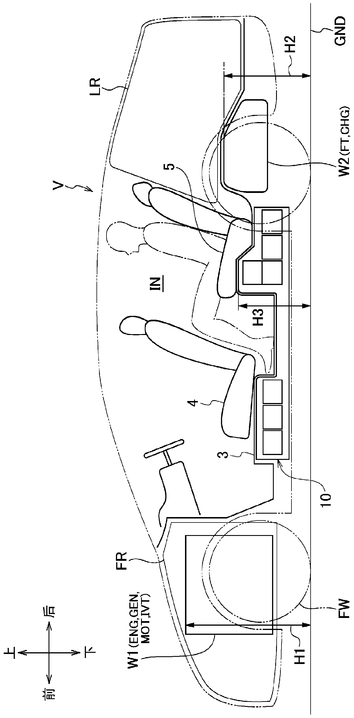
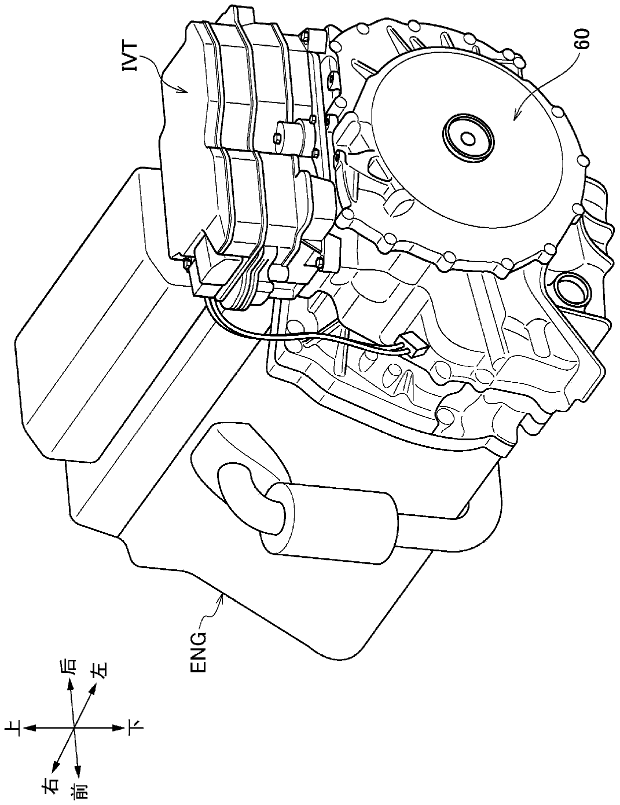
[0067] Such as figure 1 As shown, the vehicle V according to the first embodiment of the present invention is a hybrid vehicle, and includes: a compartment IN provided with front seats 4 and rear seats 5; a front compartment FR located closer to the compartment IN; The front position is provided as a space different from the compartment IN, and the luggage compartment LR is provided at a position rearward of the compartment IN as the same space as the compartment IN. It should be noted that the luggage compartment LR may be provided as a space different from the compartment IN, or may be partially connected.

[0068] Such as Figure 5 As shown, the vehicle frame 11 includes: a pair of left and right floor frames 12, 12 extending along the front and rear directions of the vehicle body; a pair of left and right front side frames 13, 13 bent upward from the front ends of the floor frames 12, 12 and extending forward; A pair of left and right rear side frames 14, 14 bent upward ...

no. 2 approach

[0090] Next, a vehicle V according to a second embodiment of the present invention will be described. It should be noted that the vehicle V of the second embodiment differs from the first embodiment only in the elements constituting the first weight portion W1 and the second weight portion W2, and the same components are given the same reference numerals and descriptions thereof are omitted.

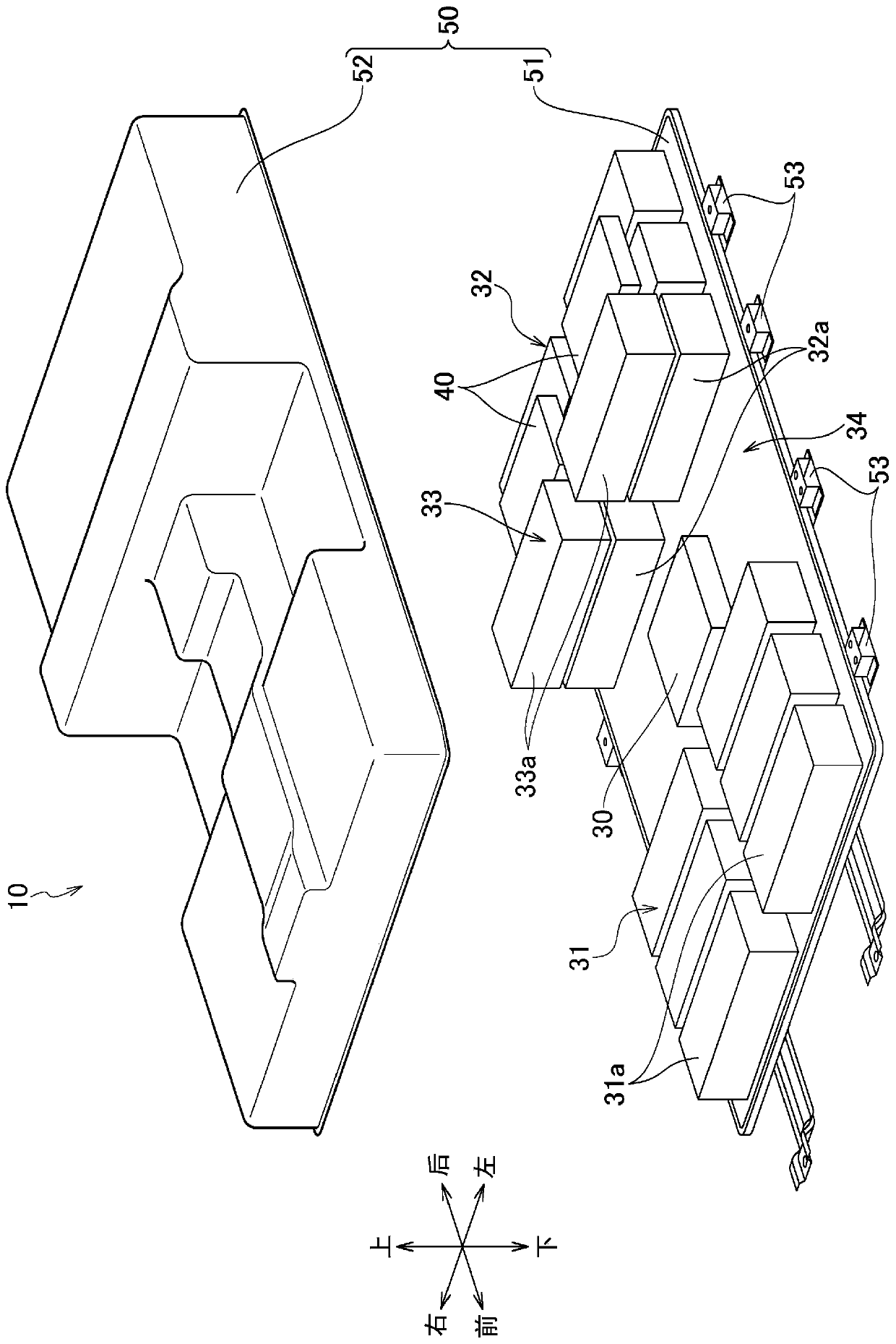
[0091] The vehicle V according to the second embodiment of the present invention is an electric vehicle, and by disposing the battery unit 10 below the floor 3 forming the floor surface of the vehicle interior IN and distributing two weight portions through the battery unit 10, the weight of the vehicle is maintained. weight balance. One of the two weight portions, the first weight portion W1 is provided in the front compartment FR, and the other, the second weight portion W2 is disposed below the luggage room LR, as in the first embodiment.

[0092] [First weight department]

[0093] Th...

no. 3 approach

[0100] Hereinafter, a vehicle V according to a third embodiment of the present invention will be described. It should be noted that the vehicle V of the third embodiment differs from the first embodiment and the second embodiment only in the structure below the cabin IN and the elements constituting the first weight portion W1 and the second weight portion W2. The same symbols are used to mark the structures of , and descriptions are omitted.

[0101] The vehicle V according to the third embodiment of the present invention is a fuel cell vehicle, and includes a fuel cell FC that generates electricity by an electrochemical reaction between hydrogen and oxygen, and two first hydrogen tanks HT1 and a second hydrogen tank that store pressurized hydrogen. In the tank HT2, the battery unit 10A and the first hydrogen tank HT1, which are smaller than the battery unit 10 of the first and second embodiments, are arranged below the floor plate 3 forming the floor surface of the vehicle i...


PUM


Abstract

Vehicle (V) has: carriage (IN); Anterior chamber (FR); Luggage (LR); The weight section, which includes at least one of the driving units that drive the front wheels (FW) and the power source that supplies fuel or electricity to that drive unit; and a battery unit (10), which supplies power to this drive unit. The weight portion has a first weight section (W1) and a second weight section (W2), and at least one of the first weight sections (W1) and the second weight section (W2) includes the drive section. The battery unit (10) is placed under the carriage, the first weight (W1) is placed in the front compartment (FR), and the second weight (W2) is placed under the trunk (LR). The height of the second weight (W2) (H2) is lower than the height of the first weight (W1) (H1).

Description

technical field [0001] The invention relates to a fuel cell vehicle, a hybrid vehicle, an electric vehicle and the like. Background technique [0002] Conventionally, there is known a vehicle in which a battery is mounted under the floor of the vehicle. For example, in the vehicle described in Patent Document 1, a battery is arranged under the cabin, and an electric motor, an inverter, and a charger are arranged in a front room provided in front of the cabin. [0003] In addition, in the vehicle described in Patent Document 2, the fuel cell and one of the two hydrogen tanks are arranged under the cabin, the electric motor is arranged in the front room provided in front of the cabin, and the luggage is placed behind the seats. The other of the two hydrogen tanks is placed under the tank, and a capacitor is placed in the trunk. [0004] prior art literature [0005] Patent Document 1: Japanese Patent No. 5104997 [0006] Patent Document 2: Japanese Patent Laid-Open No. 200...

Claims


Application Information

Patent Timeline
Patent Type & Authority Patents(China)
IPC IPC(8): B60K1/04B60K1/00B60K15/063B60K5/00B60K6/22B60K6/24B60K6/26B60L50/71H01M2/10H01M8/04B60K6/40B60L50/16B60L50/64
CPCB60K1/00B60K15/063H01M8/04201H01M2220/20H01M2250/20B60Y2400/202B60K2001/001B60K2001/0472B60K2015/0634B60K2015/0638B60L50/66B60L50/72B62D21/07B60K1/04B60K6/28B60K2001/0422B60K2001/0433B60K2001/0438B60L15/007B62D21/02Y10S903/907Y10S903/951B60L50/70B60L50/60Y02T10/64Y02T90/40Y02T10/70Y02E60/50Y02E60/10H01M50/204H01M50/249B60L50/64B60K5/00Y02T10/62B60K6/40B60K2015/0633B62D25/082B62D25/087
Inventor 高柳卓铃木浩义林正典柱山直树实吉勇一郎荻野纯一
Owner HONDA MOTOR CO LTD
Why Eureka
Try Eureka