
Front lamp mounting structure of vehicle

A technology for headlights and vehicles, which is applied to lighting devices, vehicle parts, fixed lighting devices, etc., can solve the problems of water and dust pollution, large gaps, and poor appearance quality, so as to improve precision, improve rigidity, maintain The effect of weight balance

Inactive Publication Date: 2006-01-18
HONDA MOTOR CO LTD
View PDF1 Cites 0 Cited by
  • Summary
  • Abstract
  • Description
  • Claims
  • Application Information

AI Technical Summary

Problems solved by technology

[0004] However, in the optical axis adjusting device of the above-mentioned technique for motorcycles, etc., when the optical axis of the headlight 17 is adjusted with the optical axis adjusting screws 26, 29, the headlight 17 (hereinafter referred to as "headlight") The gap between the opening 14a and the opening 14a often becomes larger due to adjustment
When the gap becomes larger, the appearance quality deteriorates, and water and dust easily invade into the front cover 14 and contaminate the inside

Method used


Image

  • Front lamp mounting structure of vehicle
  • Front lamp mounting structure of vehicle
  • Front lamp mounting structure of vehicle

Examples


Embodiment Construction

[0027] Embodiments of the present invention will be described below with reference to the accompanying drawings. "Front", "Rear", "Left", "Right", "Up", and "Down" refer to the direction seen by the driver, Fr refers to the front side, Rr refers to the rear side, L refers to the left side, and R refers to the right side . In addition, the figure surface is a figure seen from the direction of a symbol.

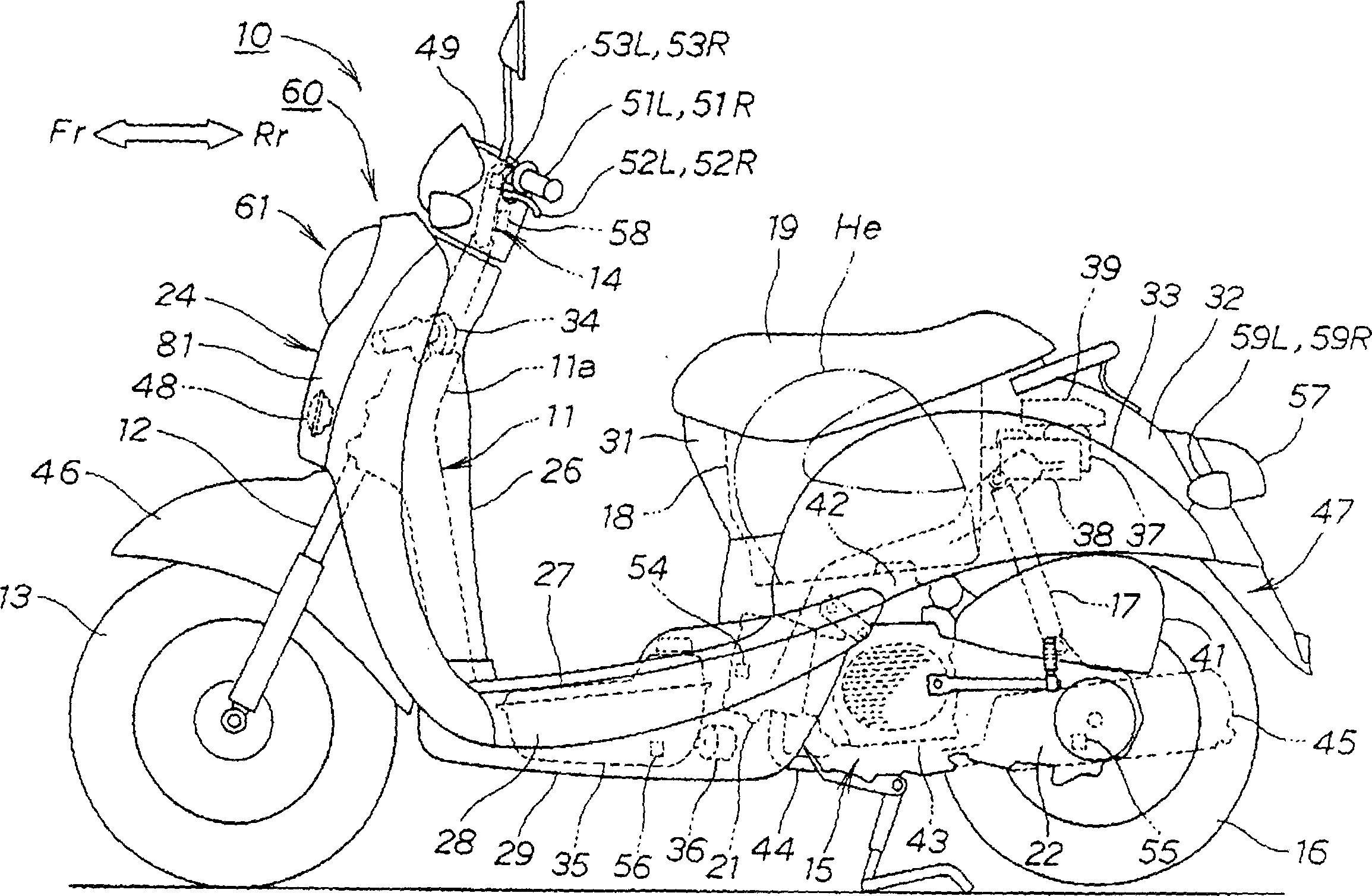
[0028] figure 1 It is a side view of a motorcycle employing the vehicle headlight mounting structure of the present invention.

[0029] The two-wheeled motor vehicle 10 is a small motorcycle type two-wheeled motor vehicle, and is mainly connected to The handle 14 on the front fork 12, the power unit 15 installed on the rear portion of the vehicle frame 11 swingably up and down, the rear wheel 16 installed on the power unit 15, the rear buffer unit 17 at the rear end of the suspension power unit 15 , a storage box 18 mounted on the rear upper portion of the vehicle frame 11,...


PUM


Abstract

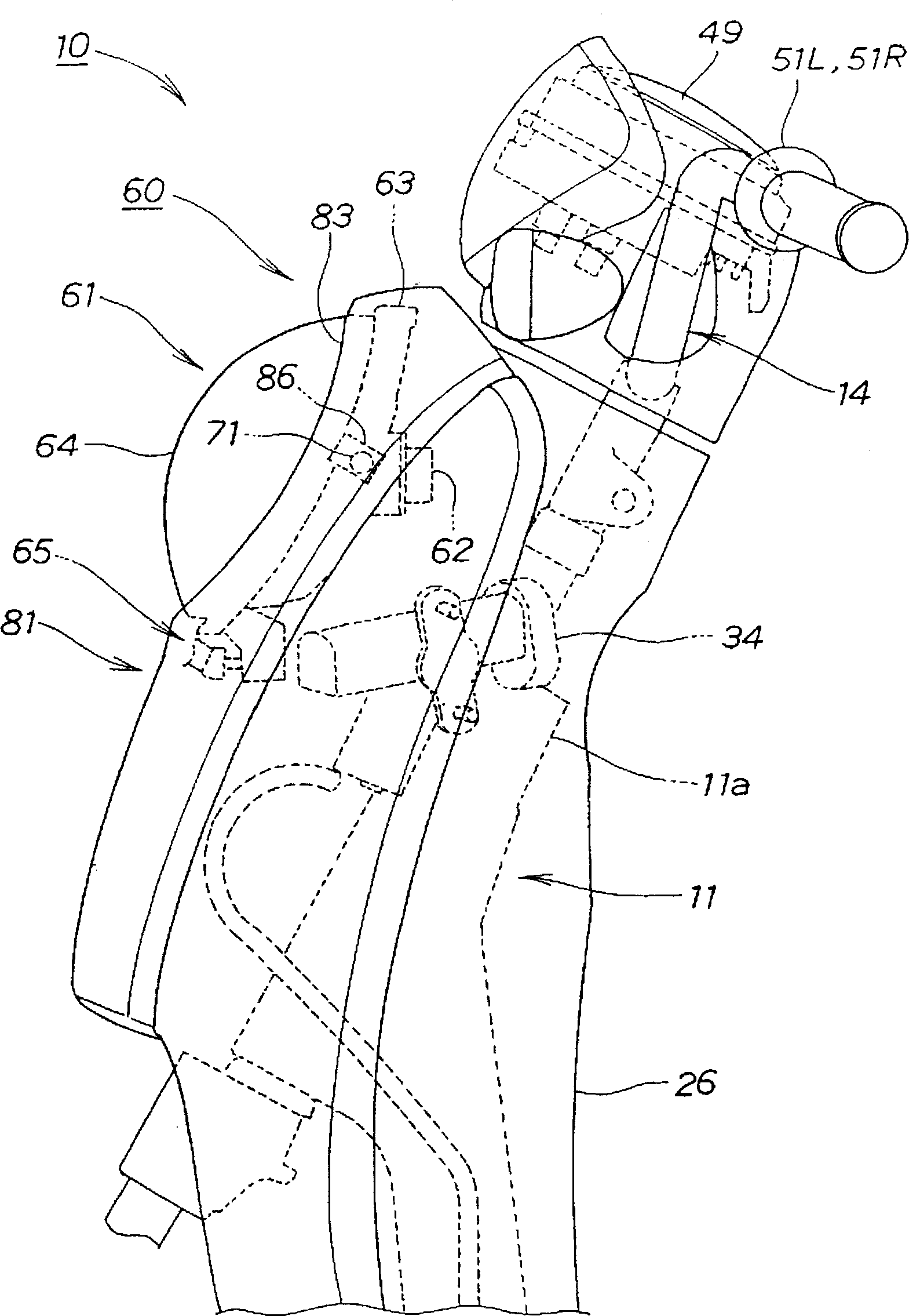
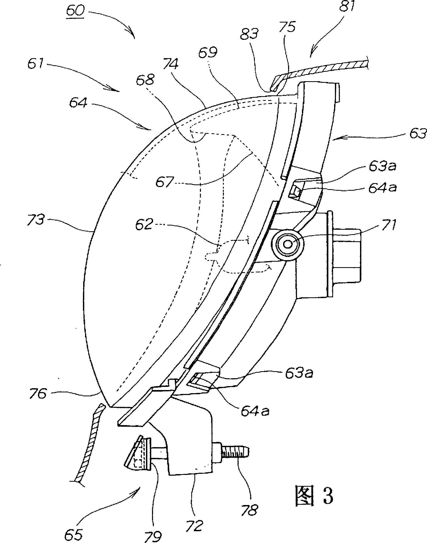
In a vehicle headlamp mounting structure in which the headlamp 61 comprising a lamp case 63 supporting a bulb 62 and including a reflecting surface and a lens 64 covering thereon is mounted so as to be capable of swinging about a supporting boss 71 (aiming shaft) with the lens exposed from the front opening 83 of a front cover 81 (vehicle body cover), the lens 64 is formed into a generally spherical surface as a whole, and is formed with spherical portions, 76 in the vicinity of the upper edge 83a and the lower edge 83b of the front opening 83 so that it follows the circular are having a center at the supporting boss 71 (aiming shaft). For example, the clearance between the lens and the front opening may be minimized. As a consequent, the design of the vehicle may be improved.

Description

technical field [0001] The present invention relates to a headlight installation structure for a vehicle in which a headlight is mounted with a pivot shaft for aiming as a swing center and a lens is exposed from a front opening of a vehicle body cover. The headlight uses a lens to block a support bulb. And equipped with a reflective lamp housing. Background technique [0002] As a vehicle headlamp mounting structure. For example, the "optical axis adjustment device for motorcycles, etc." of Japanese Patent Publication No. 6-53472 is known. [0003] According to the 6th figure of this publication, the optical axis adjusting device of the motorcycle etc. in the above-mentioned technology, an opening 14a is opened on the front cover 14, and the headlight 17 that is table-shaped when viewed from the side faces and is arranged with this opening 14a. The optical axis adjusting screws 26 and 29 of the headlight 17 are used for adjusting. [0004] However, in the optical axis adj...

Claims


Application Information

Patent Timeline
Patent Type & Authority Patents(China)
IPC IPC(8): B60Q1/06B62J6/02B60Q1/04B60Q1/068F21S8/10F21V17/00F21W101/10F21Y101/00
CPCB62J6/02B60Q1/0683
Inventor 中岛广幸
Owner HONDA MOTOR CO LTD
Learn More