Rocker arm lever flywheel rotor

A technology of flywheel rotor and rocker lever, which is applied in the field of flywheel rotor, can solve the problems of limited efficiency of magnetic field force and difficulty in saving control electric energy, etc., and achieve the effect of improving inertial force, maintaining weight balance, and ensuring smooth rotation

Inactive Publication Date: 2013-08-07
武光杰 +2
View PDF6 Cites 0 Cited by
  • Summary
  • Abstract
  • Description
  • Claims
  • Application Information

AI Technical Summary

Problems solved by technology

[0002] At present, the traditional AC and DC motors use the principle of electromagnetic induction to rotate the rotor to output torque. Due to the direct action of the magnetic field between the stator and the rotor, the efficiency of the magnetic field force is limited. When the motor output torque is determined, the control power can be saved. Difficult to achieve

Method used


Image

  • Rocker arm lever flywheel rotor
  • Rocker arm lever flywheel rotor
  • Rocker arm lever flywheel rotor

Examples


Embodiment Construction

[0021] The technical solutions of the present invention will be described in detail below in conjunction with specific embodiments.

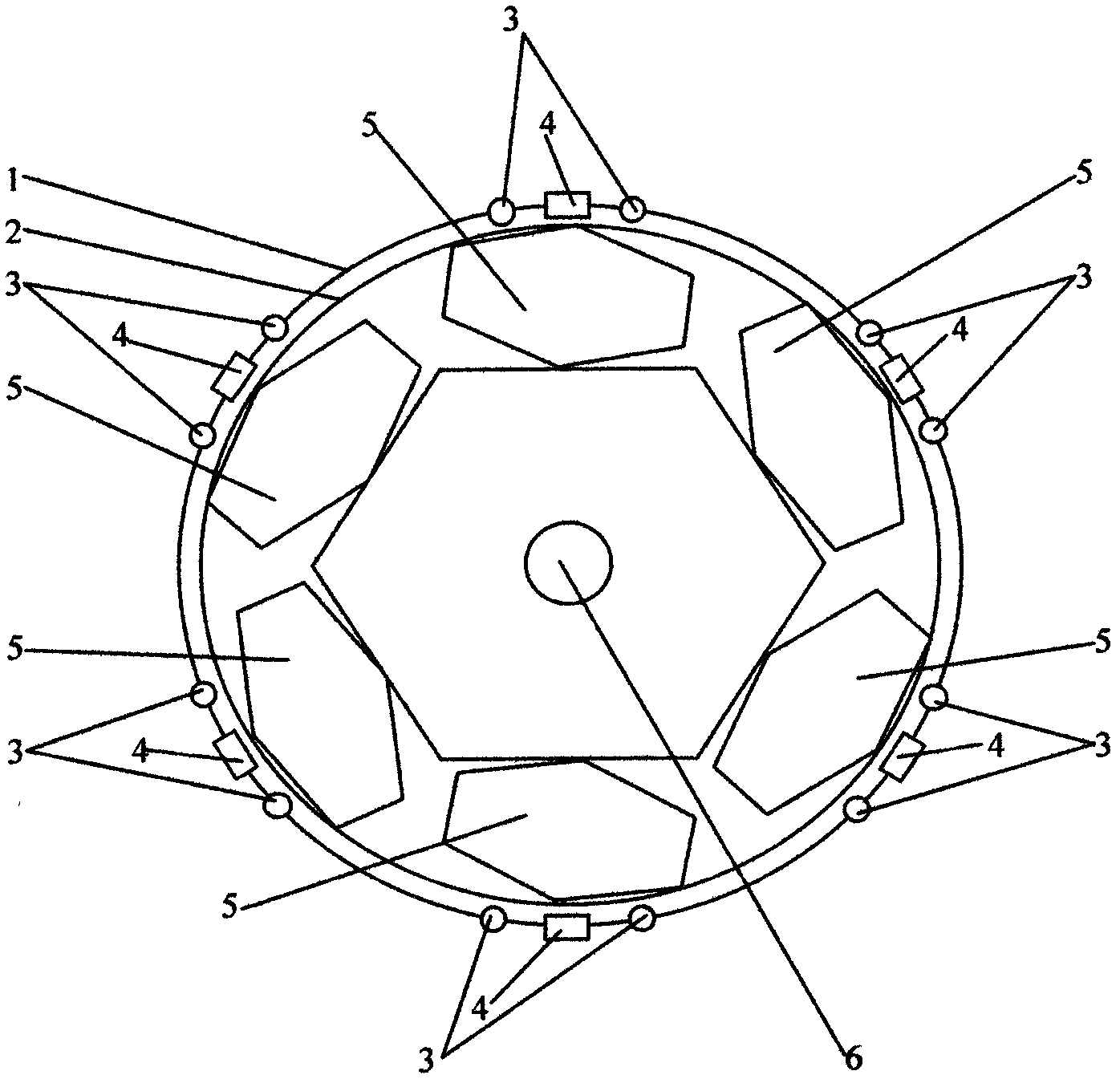
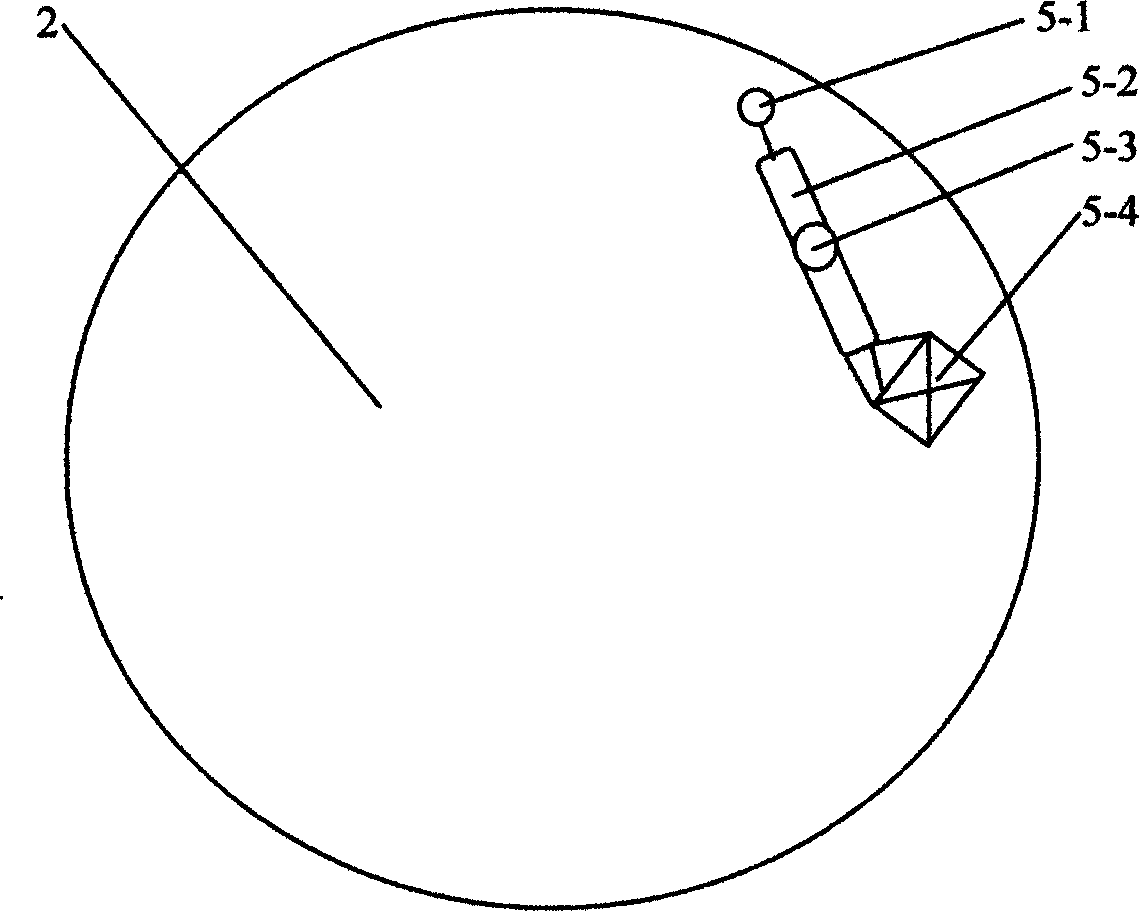
[0022] Such as Figure 1 ~ Figure 4 As shown, the rocker lever flywheel rotor in the present invention is that six rocker lever assemblies 5 are installed on a flywheel 2, and one end of the lever is fixed on the flywheel as a stress point, and the lever assembly with a rocker arm It can rotate freely on the point of force. The middle of the lever is a long chute. The fulcrum installed with the bearing is in the chute and can move. The other end of the lever is a power arm, and an iron core is installed on it, which is spherical. The electromagnetic coil and the flexible connecting rod device form the lever rocker arm, and the magnetic field force generated by the rocker arm coil and the flywheel rotor support coil 4 pulls the lever power arm and pries the flywheel rotor to rotate forward by an angle. When the flywheel rotor rotates, the lever ...


PUM


Abstract

The invention discloses a rocker arm lever flywheel rotor composed of six levers with rocker arms. The flywheel rotor is rotated by means of the inertia of the flywheel, wherein the flywheel is pried by using the attractive force and repulsive force generated by a rocker arm magnetic field as the power. The lever of the rocker arm is designed as a sliding chute structure with a stripped middle, alever fulcrum is in the sliding chute, the rocker arm performs the ellipse and inclined 8-shaped rocking in coordination with the flywheel rotation by using the lever fulcrum as the centre; when the lever fulcrum moves to the top point position of the inclined 8-shape and the lever power arm is the longest, the lever pries the flywheel to forwardly rotate with a certain angle by using the magnetic attractive force and repulsive force generated by the rocker arm and a bracket electromagnetic coil as the power. After the six rocker arm levers orderly pry the flywheel once, the flywheel rotor rotates in a circle; and the functions of flywheel rotor starting, stopping, rotary speed controlling and the like are finished by a servo circuit consisting of electron components such as a singlechip,a Hall sensor, the electromagnetic coil and the like. The rocker arm lever flywheel rotor provided by the invention is labor-saving, saves electric energy, and can replace the traditional alternating-direct current motor to drag the mechanical equipment.

Description

【Technical field】 [0001] The invention relates to a flywheel rotor for saving labor and electric energy, in particular to a rocker lever flywheel rotor. 【Background technique】 [0002] At present, the traditional AC and DC motors use the principle of electromagnetic induction to rotate the rotor to output torque. Due to the direct action of the magnetic field between the stator and the rotor, the efficiency of the magnetic field force is limited. When the motor output torque is determined, the control power can be saved. Difficult to achieve. 【Content of invention】 [0003] The purpose of the present invention is to provide a flywheel rotor that saves labor and electric energy. The flywheel is rotated with a lever to achieve the purpose of labor saving; by increasing the weight of the flywheel counterweight iron, the flywheel rotor can output a larger torque. [0004] At the same time, the interaction between the attraction and repulsion of the magnetic field is used to i...

Claims


Application Information

Patent Timeline
IPC IPC(8): H02K7/02H02N11/00
CPCY02E60/16
Inventor 武光杰崔朝晖武兴成
Owner 武光杰
Why Eureka
Try Eureka