Radar detection method, notably for airborne radars implementing an obstacle detection and avoidance function

a detection method and radar technology, applied in the field of radar detection methods, can solve the problems of not being able to optimize the efficiency of the radar waveform simultaneously, and no longer ensure the efficiency of the waveform

Active Publication Date: 2011-08-04
THALES SA
View PDF5 Cites 19 Cited by
  • Summary
  • Abstract
  • Description
  • Claims
  • Application Information

AI Technical Summary

Benefits of technology

[0016]The invention overcomes the abovementioned deficiencies. The invention includes processing and parametrization of the radar waveform to allow lossless operation whatever the delay between the ramp emitted and the demodulation ramp.

Problems solved by technology

Certain problems encountered for radar implementation of “Sense & Avoid” type may be encountered in other contexts in so far as the constraints weighing on the definition of the radar are analogous.
On the other hand, when the propagation delay for the outward-return journey is more significant than the duration of a recurrence, waveform efficiency is no longer ensured.
It is indeed impossible to simultaneously optimize the efficiency of the radar waveform and to minimize the noise related to emission leakage.

Method used


Image

  • Radar detection method, notably for airborne radars implementing an obstacle detection and avoidance function
  • Radar detection method, notably for airborne radars implementing an obstacle detection and avoidance function
  • Radar detection method, notably for airborne radars implementing an obstacle detection and avoidance function

Examples


Embodiment Construction

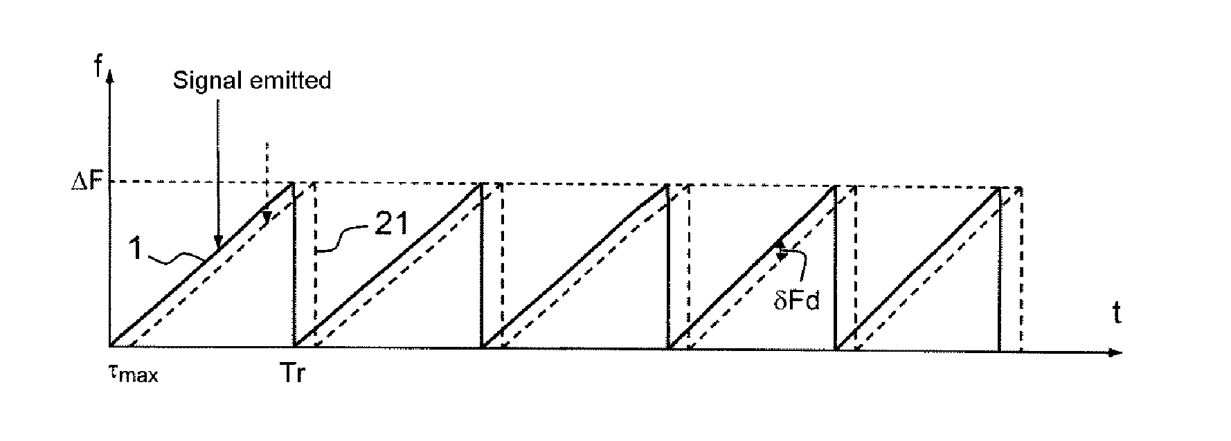
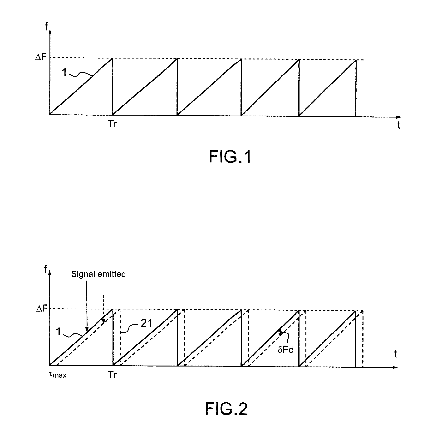
[0045]FIG. 1 presents, in a system of axes where the abscissae represent the time t and the ordinates the frequency f, a linearly modulated waveform in the form of frequency ramps 1 of amplitude, or modulation band, ΔF and of duration Tr. Such a waveform is conventionally called FMCW according to the expression “Frequency Modulation Continue Wave”.

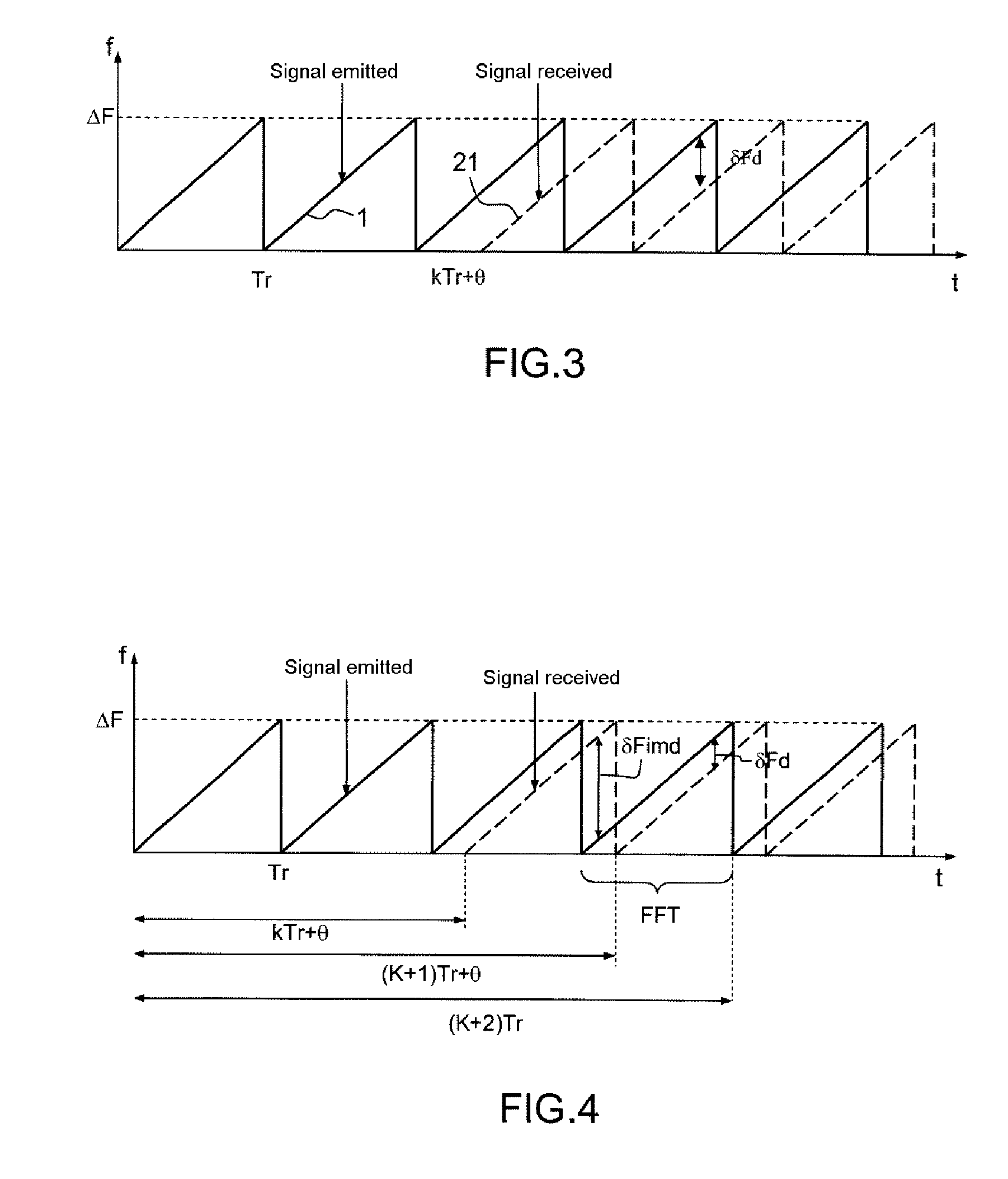
[0046]The processing of the distance measurements, at reception, includes, for each ramp, demodulating the signal received by the image of the signal emitted, sampling the signal thus demodulated, and performing a digital Fourier transform on the sampled signal. This first step makes it possible to separate the targets in the distance domain. A second Fourier transform performed from ramp to ramp makes it possible to separate the targets by Doppler processing in the speed domain.

[0047]FIG. 2 presents the waveform 21 of the signal received, in the form of frequency ramps, opposite the waveform of the signal emitted 1 of FIG. 1. The two seri...


PUM


Abstract

A method includes: generating a frequency-modulated continuous signal, an emission sequence being formed of successive ramps centred on a carrier frequency; fixing a modulation band ΔF and the duration Tr of a recurrence in such a way that at the range limit, a reception ramp appears shifted by at least one given frequency with respect to the corresponding emission ramp, on account of the propagation delay for the outward-return journey to a target kTr+θ, k being an integer and θ a duration less than Tr; demodulating the signal received by the signal emitted, the resulting signal including a first sinusoid at the frequency δFdim=(1−(θ/Tr)·ΔF and a second sinusoid at the frequency δFd=(θ/Tr)·ΔF; sampling the resulting signal and performing a first fast Fourier transformation on this resulting signal over the duration of each emission ramp; detecting in the resulting spectrum the spectral lines appearing at the frequencies δFd and δFdim, and performing the vector sum of these two spectral lines after resetting them into phase with respect to one another; and performing a detection by comparing the modulus of the vector sum with a predetermined threshold.

Description

CROSS-REFERENCE TO RELATED APPLICATION[0001]This application claims priority to foreign French patent application No. FR 09 06171, filed on Dec. 18, 2009, the disclosure of which is incorporated by reference in its entirety.FIELD OF THE INVENTION[0002]The present invention relates to a radar detection method, such as for radars in which the waveform includes a string of frequency ramps and where the propagation time for the outward-return journey to a target may be greater than the duration of an elementary ramp.[0003]The invention applies to obstacle detection and avoidance function, also called “Sense & Avoid,” with which aircraft are equipped, for example.BACKGROUND OF THE INVENTION[0004]The implementation for aircraft, in particular for drones, of a non-cooperative radar function for detecting aerial obstacles is essential to allow the insertion of autopiloted aircraft into the unsegregated airspace. It participates in the obstacle detection and avoidance function known by the n...

Claims


Application Information

Patent Timeline
Patent Type & Authority Applications(United States)
IPC IPC(8): G01S13/00
CPCG01S7/352G01S13/343G01S2007/356G01S13/9303G01S13/584G01S13/933G01S7/356
Inventor CORNIC, PASCALLE BIHAN, PATRICKKEMKEMIAN, STEPHANE
Owner THALES SA
Why Eureka
Try Eureka