Liquid crystal display device

Active Publication Date: 2011-08-04
JAPAN DISPLAY INC +1
View PDF5 Cites 14 Cited by
  • Summary
  • Abstract
  • Description
  • Claims
  • Application Information

AI Technical Summary

Benefits of technology

[0012]According to the liquid crystal display device of the present invention, the power consumpt

Problems solved by technology

Accordingly, in an attempt to acquire desired white brightness, due to a trade-off between the enhancement of the light emission efficiency of the backlight and the lowering of tra

Method used


Image

  • Liquid crystal display device
  • Liquid crystal display device
  • Liquid crystal display device

Examples


Embodiment Construction

[0019]Hereinafter, an embodiment according to the present invention is explained in conjunction with attached drawings.

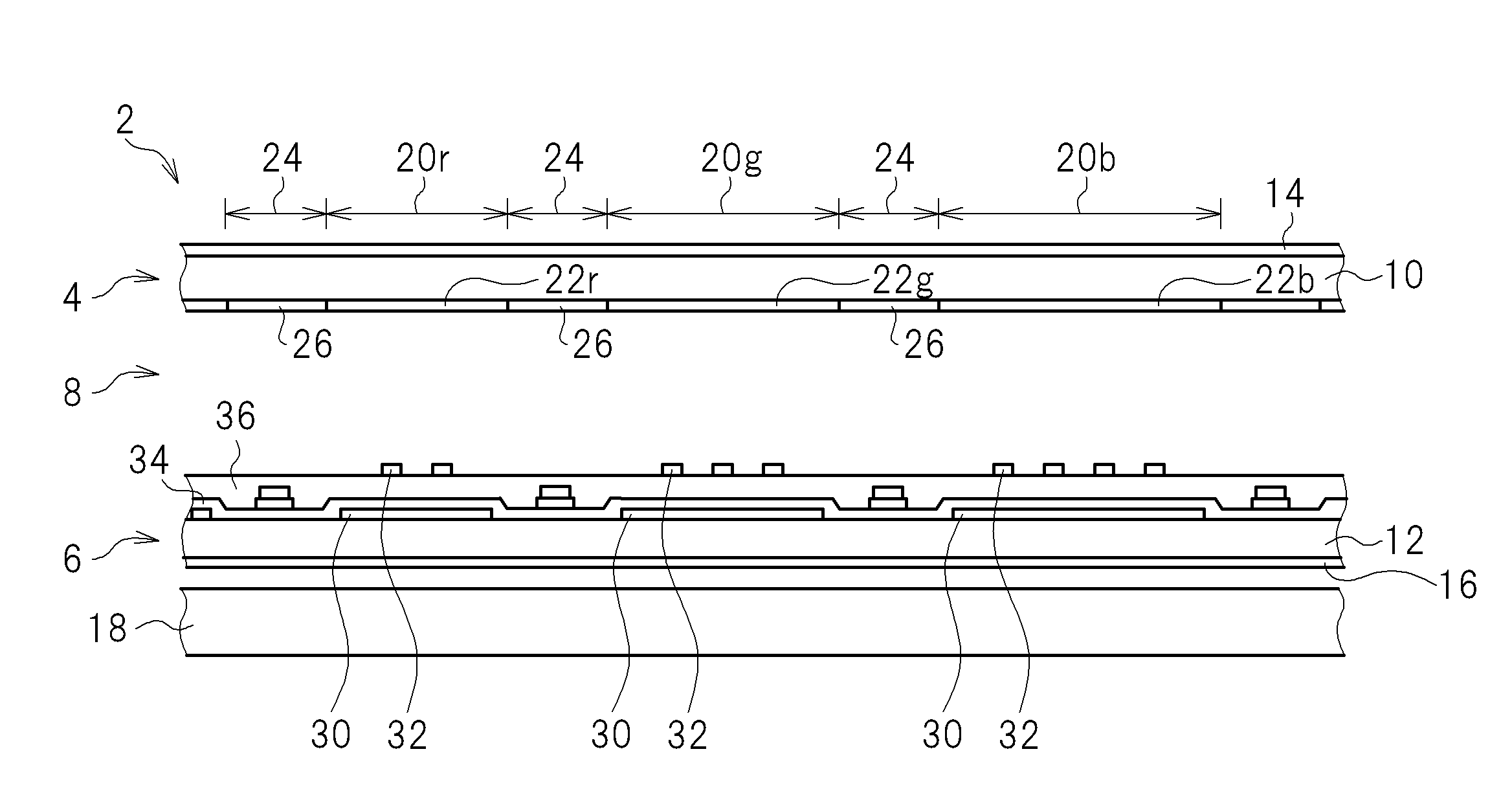
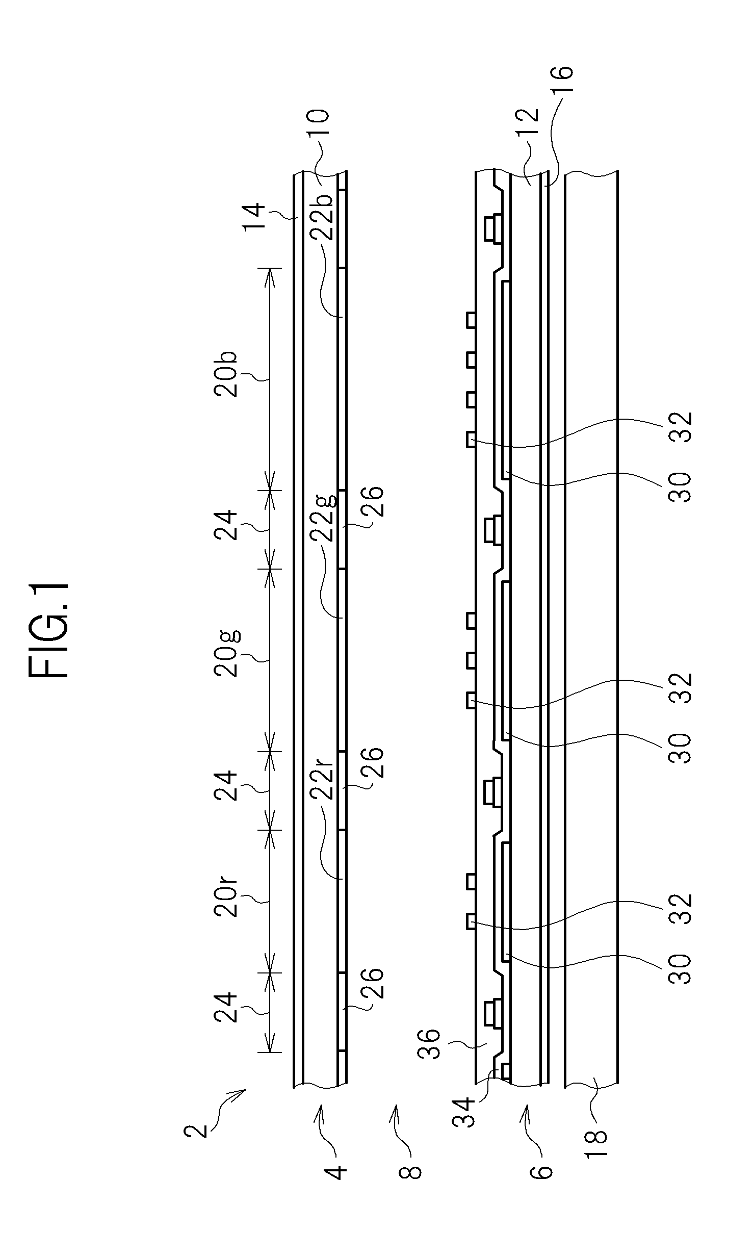
[0020]FIG. 1 is a schematic cross-sectional view of a liquid crystal display device 2 according to this embodiment. The liquid crystal display device 2 is an IPS (In Plane Switching) and active-matrix-driving liquid crystal display device, wherein liquid crystal 8 is filled between a color filter substrate 4 and a TFT (Thin Film Transistor) substrate 6. Polarizing films 14, 16 are adhered to outer surfaces of glass substrates 10, 12 which constitute the color filter substrate 4 and the TFT substrate 6 respectively. A backlight 18 is arranged in a state where the backlight 18 faces a surface of the polarizing film 16 of the TFT substrate 6. FIG. 1 is the cross-sectional view along the horizontal direction (row direction) of an image.

[0021]Each pixel is formed of a set of red, green and blue subpixels 20r, 20g, 20b. On the color filter substrate 4, a red film 22r, a g...


PUM


Abstract

In a liquid crystal display device, the reduction of power consumption is realized by reddening a backlight while maintaining a white balance. An aperture ratio of a red subpixel and an aperture ratio of a blue subpixel are set such that, in a state where an aperture ratio of a green subpixel in each pixel of a liquid crystal panel is fixed to a desired value, white brightness efficiency takes a maximum value which is set based on a balance between light emission efficiency which is increased corresponding to lowering of a color temperature of the backlight and transmissivity of the pixel which is decreased corresponding to the increase of the aperture ratio of the blue subpixel.

Description

CROSS-REFERENCE TO RELATED APPLICATION[0001]The present application claims priority from Japanese application JP 2010-018299 filed on Jan. 29, 2010, the content of which is hereby incorporated by reference into this application.BACKGROUND OF THE INVENTION[0002]1. Field of the Invention[0003]The present invention relates to a liquid crystal display device, and more particularly to a liquid crystal module including a liquid crystal panel and a backlight.[0004]2. Description of the Related Art[0005]Recently, along with the increase of interest among people on environmental problems, there has been a demand for electric appliances of low power consumption. A liquid crystal television receiver set is not an exception. In a liquid crystal module which constitutes a display part of a liquid crystal display device such as a liquid crystal television receiver set, most of power is consumed by a backlight. Accordingly, in an attempt to reduce power consumption, the enhancement of light emissi...

Claims


Application Information

Patent Timeline
IPC IPC(8): G02F1/136G02F1/1335
CPCG02F1/136G02F1/1335G02F1/133514G02F1/133614G09G3/3648G02F2201/52G02F1/133617G09G3/3406
Inventor HIYAMA, IKUOOJIMA, KENTAROISHII, MASAHIROKATOU, SHISEIMIKAMI, YOSHIRO
Owner JAPAN DISPLAY INC
Why Eureka
Try Eureka