
Coupled system multi-core fiber, coupling mode multiplexer and demultiplexer, system for transmission using multi-core fiber and method for transmission using multi-core fiber

Inactive Publication Date: 2011-08-04
NAT UNIV CORP YOKOHAMA NAT UNIV +1
View PDF8 Cites 32 Cited by
  • Summary
  • Abstract
  • Description
  • Claims
  • Application Information

AI Technical Summary

Benefits of technology

[0045]As described above, the present invention makes it possible to carry out mode multiplexing transmission using, not a multi-mode fiber, but a multi-core fiber that contains multiple single-mode cores in one optical fiber.

Problems solved by technology

That is, the technologies described in those documents are not those for increasing the transmission capacity to the maximum.

Method used


Image

  • Coupled system multi-core fiber, coupling mode multiplexer and demultiplexer, system for transmission using multi-core fiber and method for transmission using multi-core fiber
  • Coupled system multi-core fiber, coupling mode multiplexer and demultiplexer, system for transmission using multi-core fiber and method for transmission using multi-core fiber
  • Coupled system multi-core fiber, coupling mode multiplexer and demultiplexer, system for transmission using multi-core fiber and method for transmission using multi-core fiber

Examples


Embodiment Construction

[0068]A preferred embodiment of the present invention will be described in detail below with reference to the drawings.

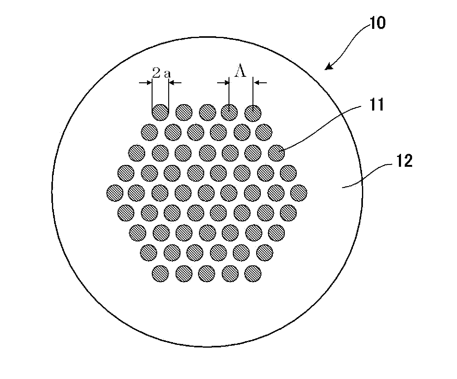
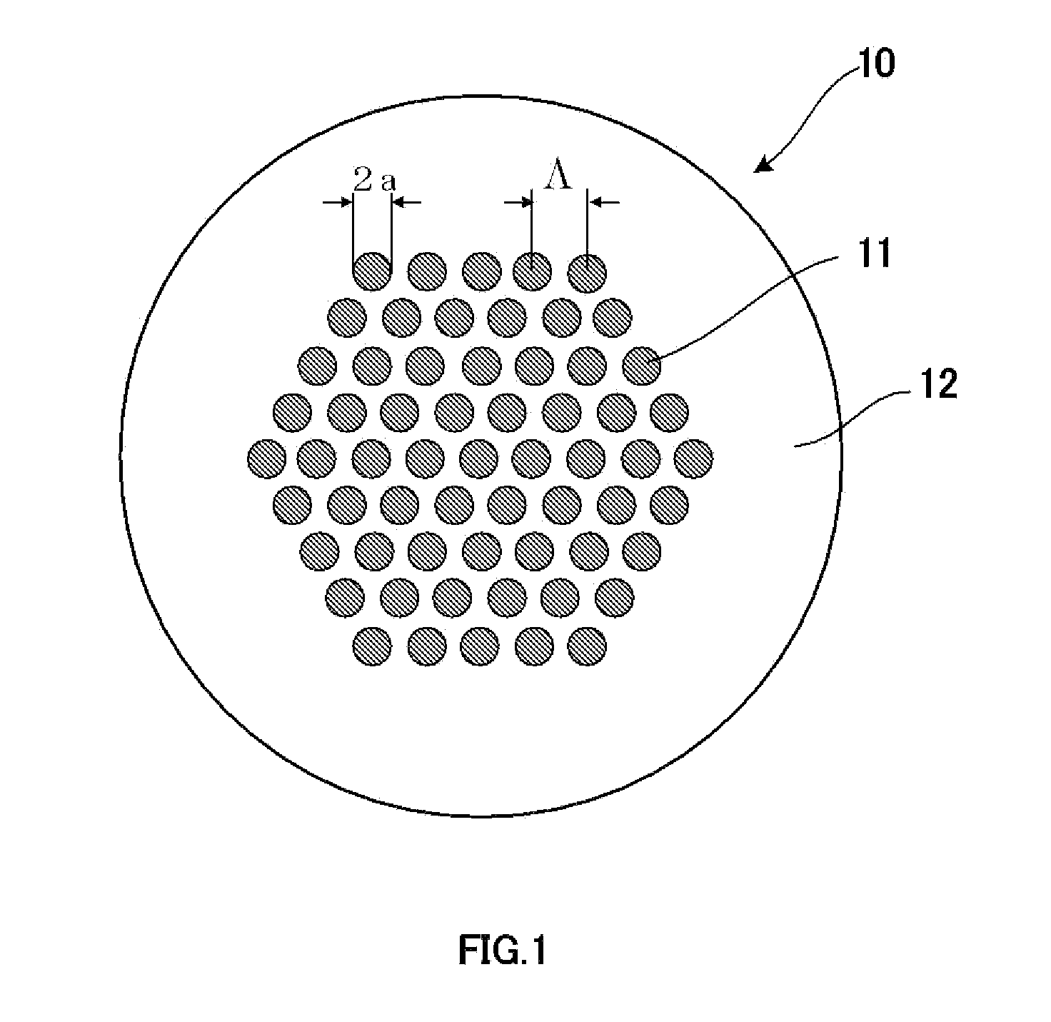
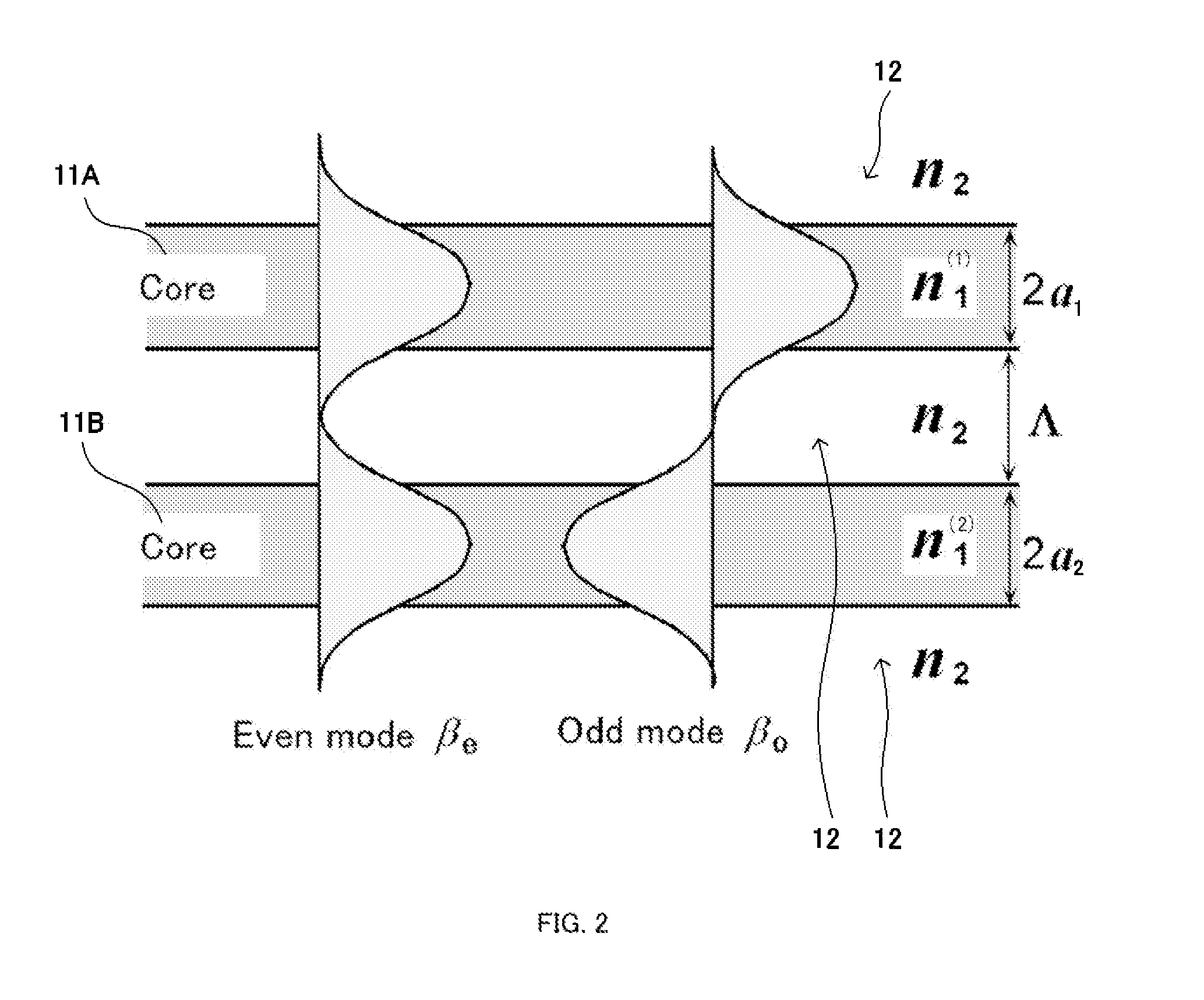
[0069]The following describes a multi-core fiber, more specifically, a coupled multi-core fiber, of the present invention with reference to FIG. 1 to FIG. 9.

[0070]A multi-core fiber having homogeneous cores, all of which have an equal propagation constant, is called a “Homogeneous Multi-core Fiber (Homogeneous MCF)”, while a fiber having multiple cores, which have different propagation constants, is called a “Heterogeneous Multi-core Fiber (Heterogeneous MCF)”. The present invention relates to a coupled multi-core fiber, and a “Homogeneous Multi-core Fiber (Homogeneous MCF)” will be described below.

[0071][Coupled Multi-Core Fiber]

[0072]For the core arrangement of a coupled multi-core fiber, the most closely packed arrangement that ensures the highest core density is the triangular arrangement such as that shown in FIG. 1. In the triangular arrangement shown in FIG. ...


PUM


Abstract

The multi-core fiber of the present invention uses a multi-core fiber configuration, compatible with the “coupled” operation mode in which coupling between cores is positively utilized, to carry out mode division multiplexing transmission via a multi-core fiber that contains multiple single-mode cores in one optical fiber. The multi-core fiber of the present invention uses a configuration in which mode multiplexing transmission is carried out using a multi-core fiber that contains multiple single-mode cores in one optical fiber, wherein multiple cores are strongly coupled intentionally to form a coupled multi-core fiber that makes the coupled modes correspond, one to one, to the transmission channels.

Description

TECHNICAL FIELD[0001]The present invention relates to a multi-core fiber suitable for mode multiplexed transmission, and more particularly to a coupled multi-core fiber and a mode multiplexer / demultiplexer at the input and output ends of the coupled multi-core fiber and to a multi-core fiber transmission system that uses both mode division multiplexing and space division multiplexing where a coupled / uncoupled hybrid multi-core fiber is used for high-density space division multiplexing with multiple coupled multi-core groups in the uncoupled state.BACKGROUND ART[0002]Conventionally, study has been conducted on a multi-mode fiber, and many methods have been proposed for solving a transmission capacity limitation caused by a mode group delay difference. One of the proposed methods is that the mode groups are separated for electrically equalizing the group delay difference (Non-Patent Document 1). After that, based on the fact that the mode propagation angle corresponds approximately to...

Claims


Application Information

Patent Timeline
Patent Type & Authority Applications(United States)
IPC IPC(8): H04J14/00G02B6/26
CPCG02B6/2804G02B6/02042H04B10/2581H04J14/052H04J14/04
Inventor KOKUBUN, YASUOKOSHIBA, MASANORIMORIOKA, TOSHIO
Owner NAT UNIV CORP YOKOHAMA NAT UNIV
Learn More