Elastic-cushioned capacitively-coupled connector

Inactive Publication Date: 2011-08-04
MOLEX INC
View PDF11 Cites 4 Cited by
  • Summary
  • Abstract
  • Description
  • Claims
  • Application Information

AI Technical Summary

Benefits of technology

[0029]Further, in this aspect, at least on one of a part of the first opposing conductor portions and the second opposing conductor portions, there may be formed a protrusion protruding toward the other. With this construction, it is possible to enhance the press-bonding force between the first opposing conductor portions and the second opposing conductor portions, which is suitable for use such as power supply.
[0030]The first frame has a detachment prevention portion extending toward the second frame side, and the second frame has an elastic member elastically deformable along the second flat circuit substrate and adapted to press the detachment prevention portion against some other portion of the second frame. With this construction, the elastic member for pressing the detachment prevention portion is elastically deformably formed along the second flat circuit substrate, and hence it is possible to achieve a reduction in height of the connector.
[0031]An opening may be formed in the second frame, and the elastic member may press the detachment prevention portion inserted into the opening

Problems solved by technology

There is hence a fear of a desired characteristic not being maintained whe

Method used


Image

  • Elastic-cushioned capacitively-coupled connector
  • Elastic-cushioned capacitively-coupled connector
  • Elastic-cushioned capacitively-coupled connector

Examples


Example

[0103]A second embodiment of a terminal assembly 23B, is shown in FIGS. 12A-C and the assembly has a terminal formation body 26 attached to an elastic body 273 formed of silicone rubber or the like. The terminal formation body 26 has a first plate-like portion 274 and second plate-like portions 275 formed by resin sheets formed of polyimide or the like, and a plurality of first strip-like terminals 25 bridge therebetween. More specifically, on both lateral sides of the first plate-like portion 274, there are arranged the second plate-like portions 274 at a predetermined interval, and the first terminals 25 extend laterally from the first plate-like portion 274 to the second plate-like portions 275. The first terminals 25 are formed on terminal formation surfaces 274a, 275b of the first plate-like portion 274 and the second plate-like portions 275. Further, the first plate-like portion 274 has lining layers 274f lined with the first terminals 25 and extending together with them towar...

Example

[0109]Next, a third embodiment of a terminal assembly 23C is shown in FIGS. 16A-16C.

[0110]As shown in FIGS. 16A through 16C, in the terminal assembly 23C, a pair of first opposing conductor portions 25x of the plurality of first opposing conductor portions 25a have protrusions 251x protruding on the front side (the second opposing conductor portions 35a side). As shown in FIGS. 17A and 17B, of the plurality of second opposing conductor portions 35a, second opposing conductor portions 35x corresponding to the first opposing conductor portions 25x have no dielectrics portions 4. Thus, the first opposing conductor portions 25x and the second opposing conductor portions 35x are connected directly to each other with no dielectrics portions 4 formed therebetween. Further, since the protrusions 251x are provided on the first opposing conductor portions 25x, when the first and second connector frames 21, 31 are attached together, the amount by which the elastic member 27 is compressed by th...


PUM


Abstract

A connector according to the present invention is equipped with an elastic member with elasticity, at least one terminal including a connecting conductor portion formed on one side of the elastic member and connected to a circuit side conductor portion electrically continuous with a circuit provided on a first flat circuit substrate, a first opposing conductor portion formed on another side of the elastic member and opposed to a second opposing conductor portion electrically continuous with a circuit provided on a second flat circuit substrate, and a linking conductor portion linking the connecting conductor portion and the first opposing conductor portion with each other so as to allow them to make relative movement, and a dielectric portion formed at least on one of the first opposing conductor portion 25a and the second opposing conductor portion.

Description

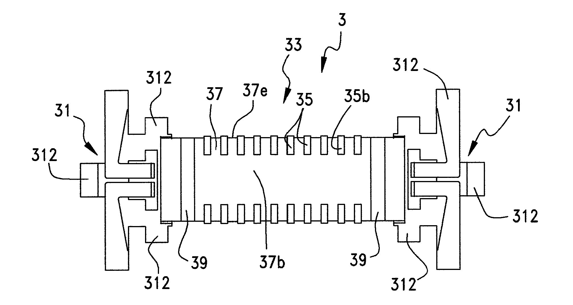
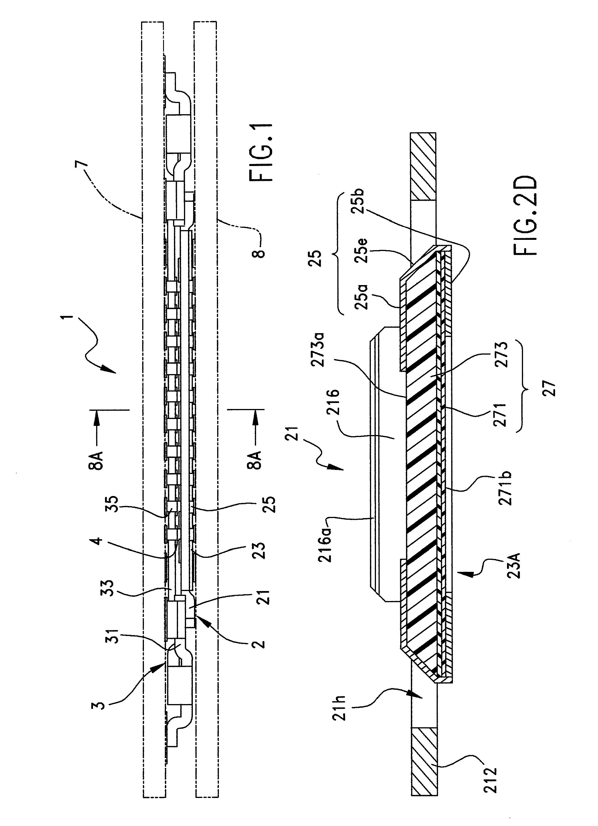
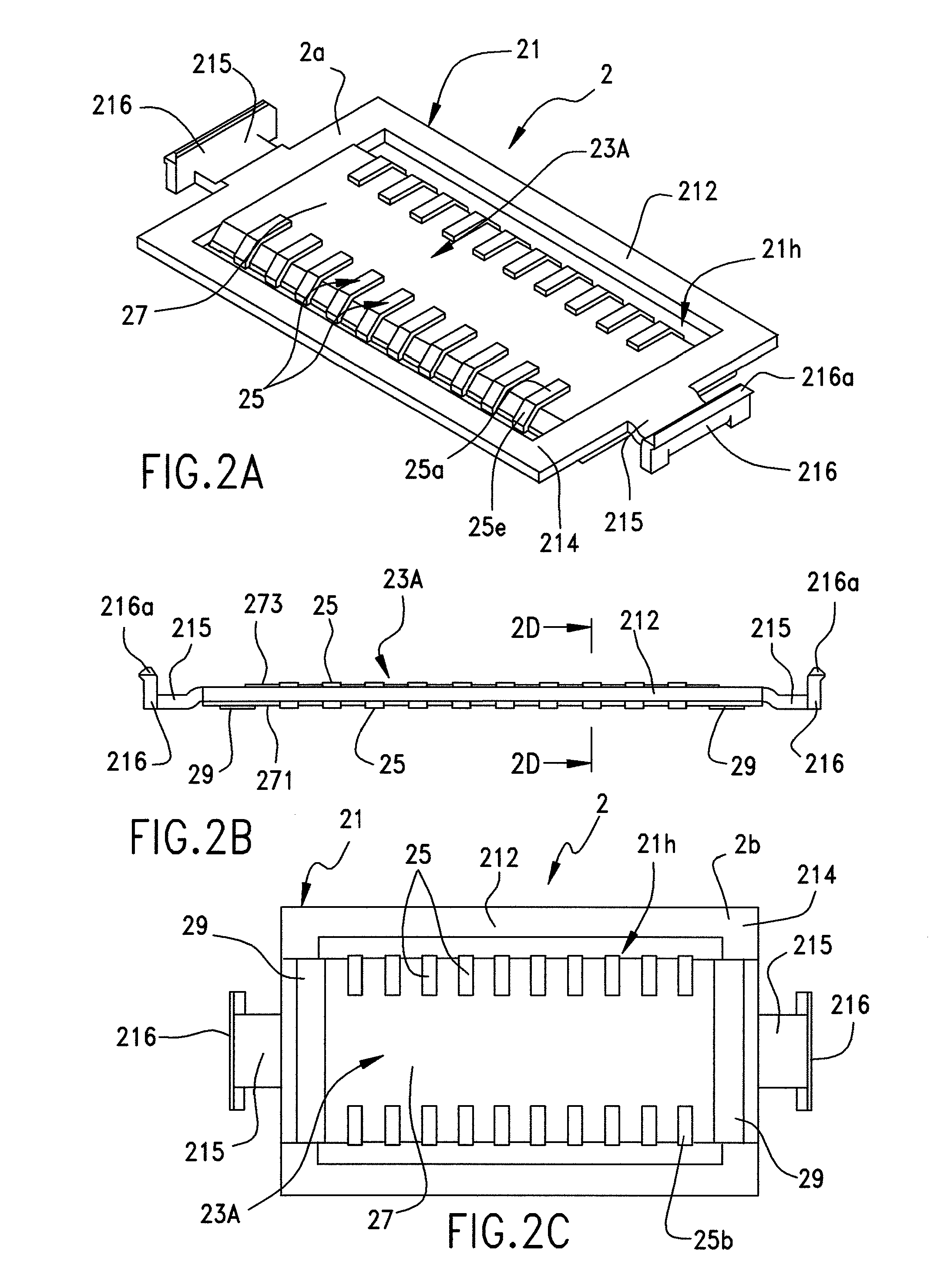
BACKGROUND OF THE INVENTION[0001]The present invention relates to a connector and a terminal holder, and more particularly, to a connector utilizing capacitive-coupling to transfer signals within the structure of a connector.[0002]In recent years, electronic apparatuses have been increased in frequency, and, as a result, non-contact signal transmission is required of a connector for use in electronic apparatuses. Known examples of such non-contact signal transmission include signal transmission through capacitive-coupling and signal transmission through electromagnetic induction.[0003]To this point, Japanese Patent Application No. JP 2002-289309 A discloses capacitive-coupling terminals provided to one connector and terminals provided to another connector by opposing each other across a spatial interval. This patent application is an example in which a dielectric is disposed between the terminals opposed to each other across the spatial interval.[0004]When arranging a dielectric bet...

Claims


Application Information

Patent Timeline
IPC IPC(8): H01R12/61
CPCH05K1/0239H05K2201/10189H05K3/368H05K3/32
Inventor NIITSU, TOSHIHIRONISHIKAWA, MASAKO
Owner MOLEX INC
Why Eureka
Try Eureka