Vehicle-collision simulation testing apparatus

Inactive Publication Date: 2011-08-11
MITSUBISHI HEAVY IND LTD
View PDF2 Cites 31 Cited by
  • Summary
  • Abstract
  • Description
  • Claims
  • Application Information

AI Technical Summary

Benefits of technology

[0023]According to the vehicle-collision simulation testing apparatus according to the present invention, because an eccentric weight unit is provided on a side of a rotation shaft of a yawing sled on

Problems solved by technology

However, a method of taking a dummy on a real vehicle and colliding the vehicle into a

Method used


Image

  • Vehicle-collision simulation testing apparatus
  • Vehicle-collision simulation testing apparatus
  • Vehicle-collision simulation testing apparatus

Examples


Example

First Embodiment

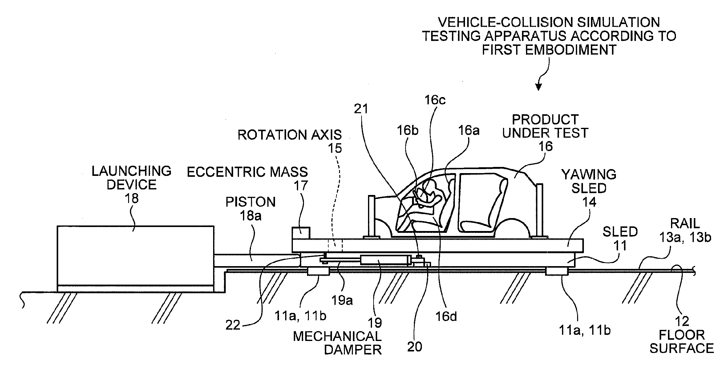
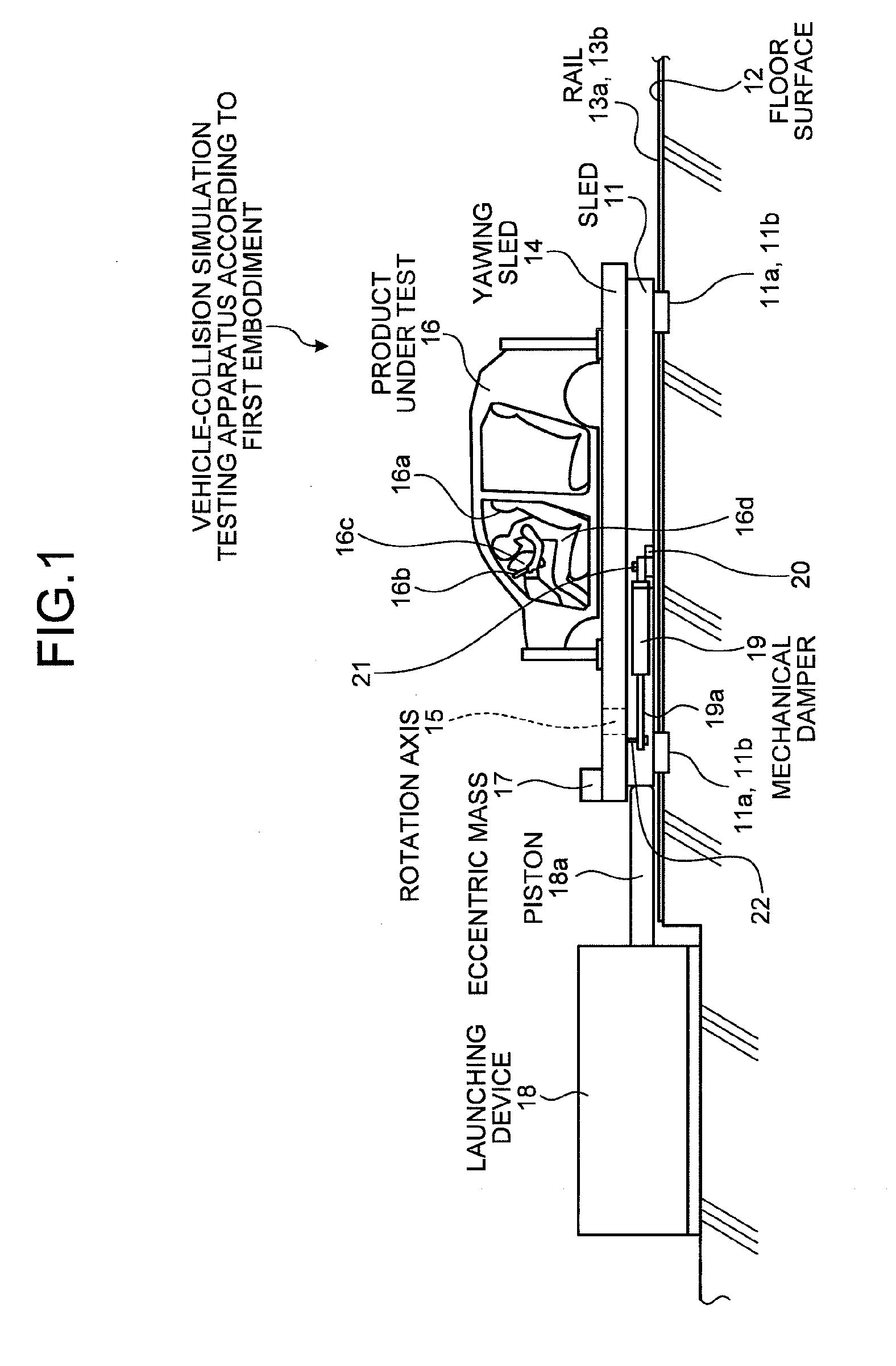
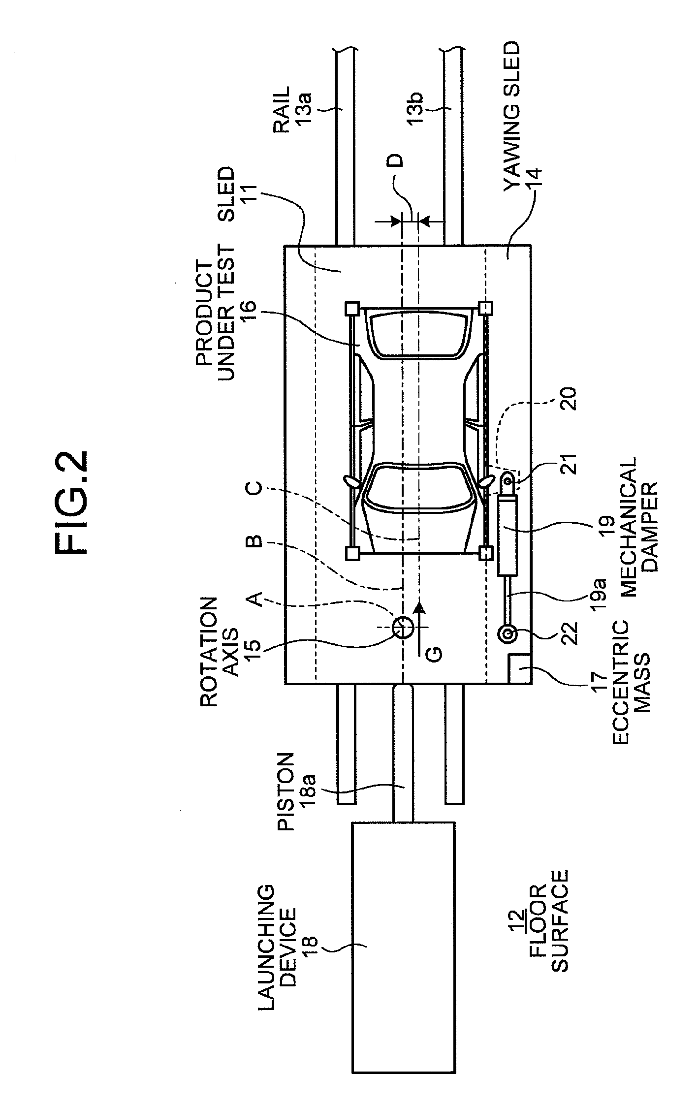
[0034]FIG. 1 is a side view of a vehicle-collision simulation testing apparatus according to a first embodiment of the present invention, FIG. 2 is a plan view of the vehicle-collision simulation testing apparatus according to the first embodiment, and FIG. 3 is a plan view of an operation of the vehicle-collision simulation testing apparatus according to the first embodiment.

[0035]In the vehicle-collision simulation testing apparatus according to the first embodiment, as shown in FIGS. 1 and 2, a sled 11 as a pedestal is a frame having a predetermined thickness, forming a rectangular shape elongated in a back-and-forth direction in its planar view (the horizontal direction in FIGS. 1 and 2). A pair of right and left rails 13a and 13b with a predetermined distance is installed on a floor surface 12 along the back-and-forth direction, so that the sled 11 is supported in a movable manner along the rails 13a and 13b via sliders 11a and 11b fixed on its bottom surface.

[0...

Example

Second Embodiment

[0057]FIG. 4 is a plan view of a vehicle-collision simulation testing apparatus according to a second embodiment of the present invention. Members having functions identical to those described in the above embodiment are denoted by like reference numerals and redundant explanations thereof will be omitted.

[0058]As shown in FIG. 4, in the vehicle-collision simulation testing apparatus according to the second embodiment, the sled 11 is supported in a movable manner along a pair of right and left rails 13a and 13b installed on the floor surface 12. The yawing sled 14 is arranged on the sled 11, with a front portion supported by the sled 11 via the rotation axis 15 so that it can make a rotation in the horizontal direction around the rotation shaft A. The product under test 16 can be mounted on an upper surface of the yawing sled 14 with a predetermined offset amount D.

[0059]The eccentric mass 17 is provided on the yawing sled 14 on a side of the rotation axis 15 (the r...

Example

Third Embodiment

[0066]FIG. 5 is a side view of a vehicle-collision simulation testing apparatus according to a third embodiment of the present invention. Members having functions identical to those described in the above embodiments are denoted by like reference numerals and redundant explanations thereof will be omitted.

[0067]As shown in FIG. 5, in the vehicle-collision simulation testing apparatus according to the third embodiment, the sled 11 is supported in a movable manner along a pair of right and left rails 13a and 13b installed on the floor surface 12. The yawing sled 14 is arranged on the sled 11, with a front portion supported by the sled 11 via the rotation axis 15 so that it can make a rotation in the horizontal direction around the rotation shaft A. The product under test 16 can be mounted on an upper surface of the yawing sled 14 with a predetermined offset amount D. The eccentric mass 17 is further provided on the yawing sled 14 on a side of the rotation axis 15 (the ...


PUM


Abstract

[Object] In a vehicle-collision simulation testing apparatus, to make it possible to downsize the apparatus with lightweight.
[Solution] A sled 11 is supported in a movable manner in a back-and-forth direction, a yawing sled 14 is arranged on the sled 11 in a horizontally rotatable manner with a front portion supported by a rotation shaft, on which a product under test can be mounted, an eccentric mass 17 is arranged on a side of a rotation shaft on the yawing sled 14, and a launching device 18 that applies a backward acceleration on a front side of the sled 11.

Description

TECHNICAL FIELD[0001]The present invention relates to a vehicle-collision simulation testing apparatus for replicating an acceleration generated inside a vehicle at the time of a collision and replicating damage on a passenger by a secondary collision, without destroying the vehicle.BACKGROUND ART[0002]Generally, a collision test of a vehicle is conducted by a full-scale collision test for evaluating a physical amount such as a crash amount and a residual space amount inside a vehicle and a damage value on a passenger. However, a method of taking a dummy on a real vehicle and colliding the vehicle into a barrier at a predetermined speed is a destructive test, which requires a very high cost. Therefore, a vehicle-collision simulation test is performed instead by loading a white body equipped with a dummy, an airbag and the like and a simulation vehicle (hereinafter, “product under test”) on a dolly and applying an acceleration with substantially the same level as in a real vehicle co...

Claims


Application Information

Patent Timeline
IPC IPC(8): G01M17/00
CPCG01M17/0078G01M17/007G01M7/08
Inventor AIKI, JUNICHI
Owner MITSUBISHI HEAVY IND LTD
Why Eureka
Try Eureka