Eureka AIR delivers breakthrough ideas for toughest innovation challenges, trusted by R&D personnel around the world.

Automatic gain stabilization and temperature compensation for organic and/or plastic scintillation devices

a technology of organic and/or plastic scintillation devices and gain stabilization, which is applied in the direction of instruments, liquid/fluent solid measurements, x/gamma/cosmic radiation measurement, etc., can solve the problems of indistinguishable photopeaks, temperature related scintillation devices, and ionizing radiation measurement devices

Active Publication Date: 2011-08-11
VEGA GRIESHABER GMBH & CO
View PDF12 Cites 21 Cited by
  • Summary
  • Abstract
  • Description
  • Claims
  • Application Information

AI Technical Summary

Benefits of technology

[0014]In some embodiments, the second output may also be responsive to a naturally occurring source of high energy beta and gamma ionizing radiation when the second scintillation material is a compound of Lutetium, such as LYSO, or LSO.

Problems solved by technology

Unfortunately, there are several disadvantages with conventional ionizing radiation measurement devices, particularly those devices using scintillating material as a radiation detector.
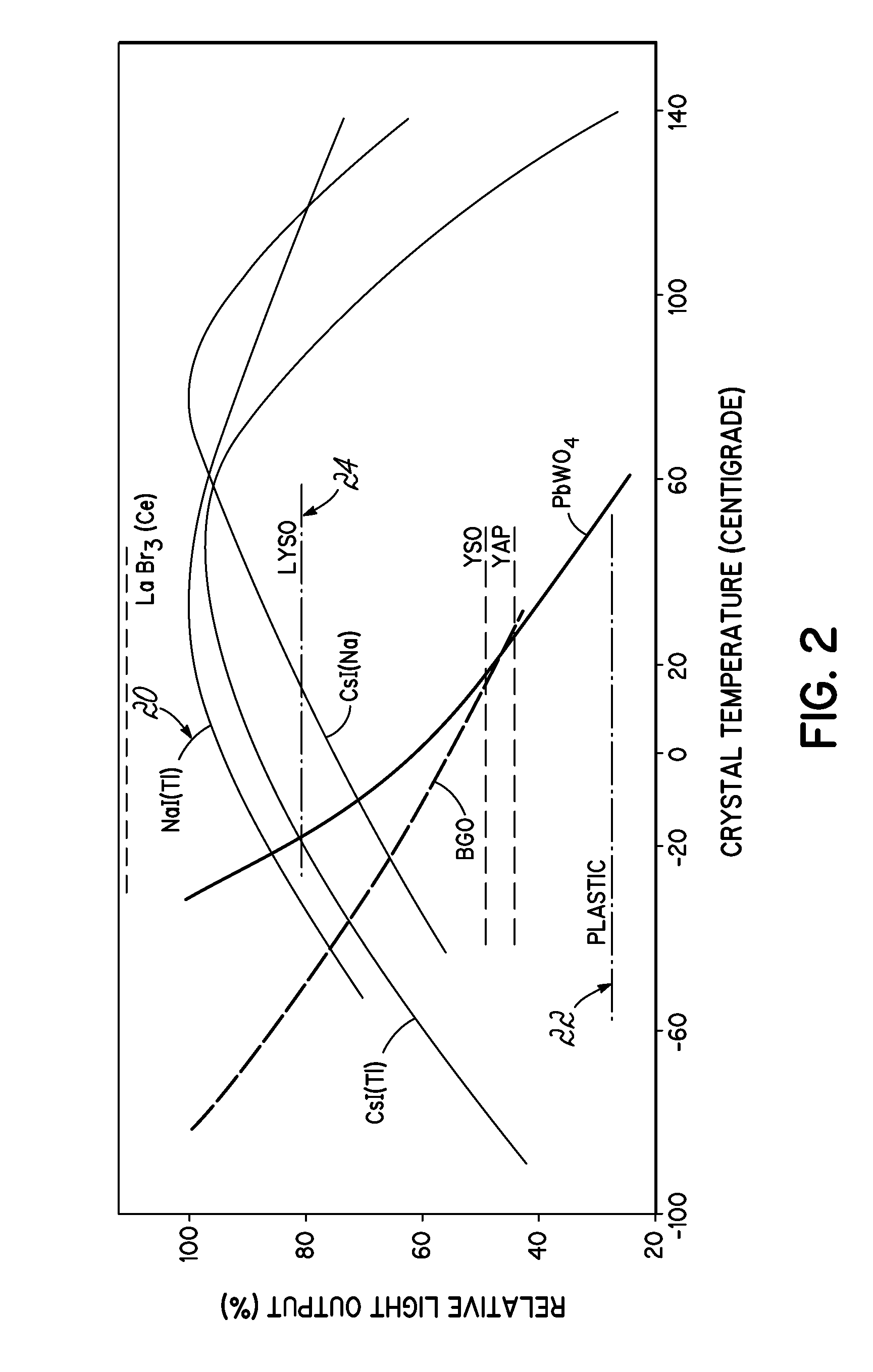
Other factors such as dark current pulses may be issues , but the primary disadvantage of a scintillation device is temperature related.
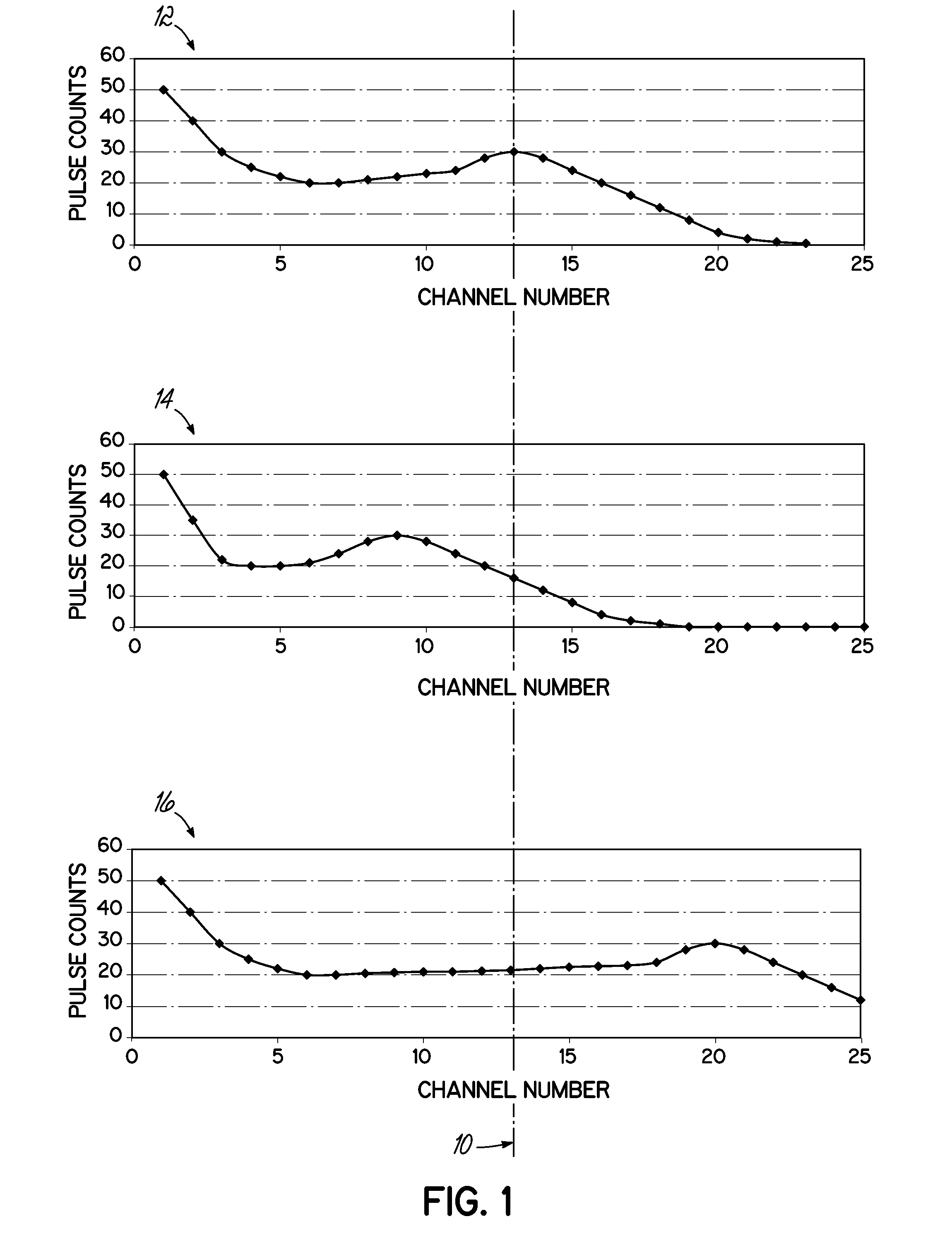
However in the case of low Z, organic and / or plastic scintillation detectors, photopeaks, if present, are not distinguishable.
Therefore temperature compensation and / or auto gain stabilization, based on the photopeak detection methods used for NaI scintillation, is not applicable to plastic or organic scintillation devices.
Plastic and organic scintillating materials generally have a relatively stable light yield over a temperature range from −60° C. to 40° C. However, the PMT gain shift over temperature is still enough of an issue to mandate temperature compensation.

Method used


Image

  • Automatic gain stabilization and temperature compensation for organic and/or plastic scintillation devices
  • Automatic gain stabilization and temperature compensation for organic and/or plastic scintillation devices
  • Automatic gain stabilization and temperature compensation for organic and/or plastic scintillation devices

Examples


Embodiment Construction

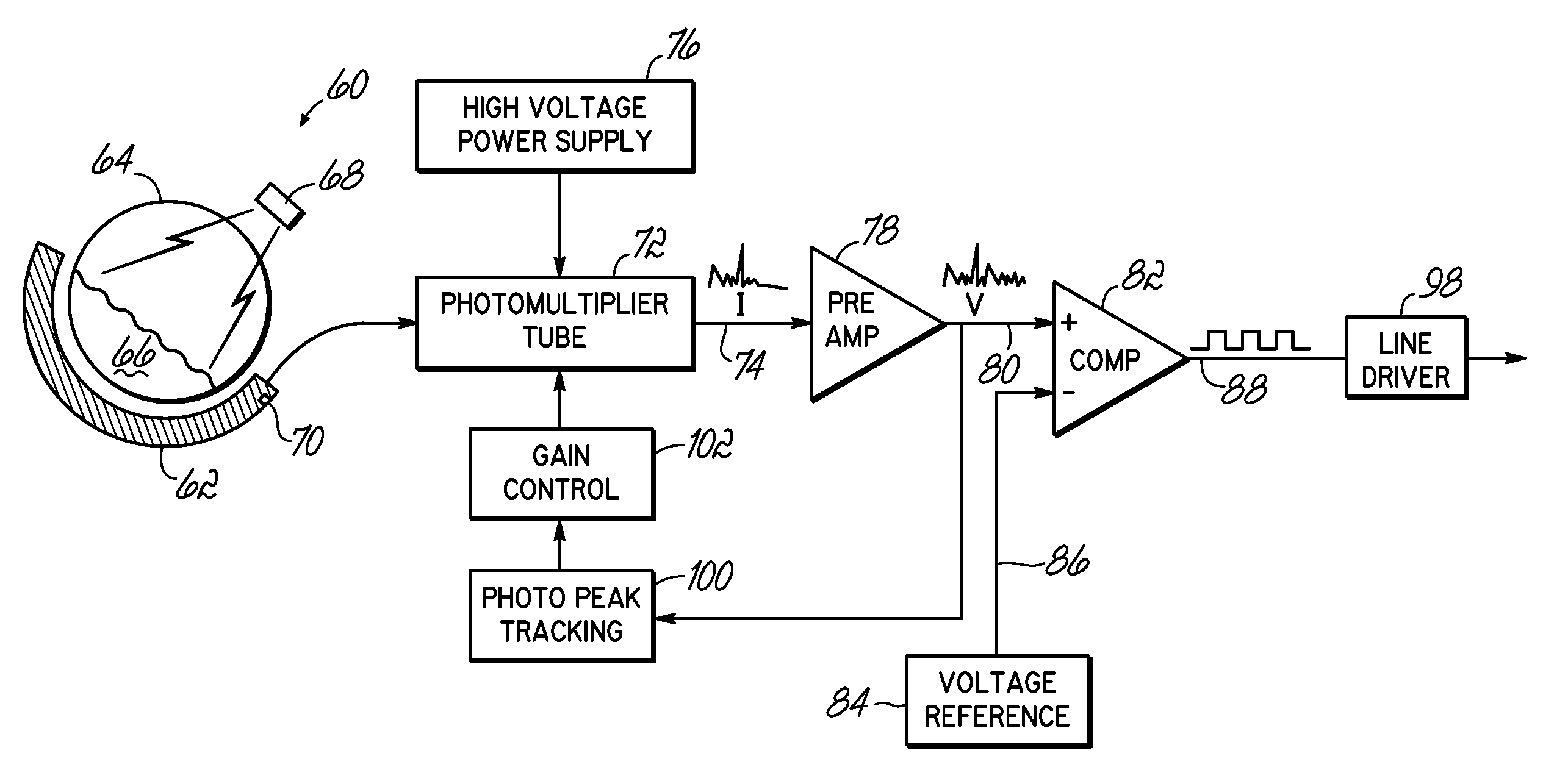
[0022]Inexpensive plastic scintillators are popular because they may easily be machined into practically any shape, including fibers, bars, etc. Furthermore, the advance of technology in the production of robust and reliable photomultiplier tubes assists in making application of scintillation detectors for measurements in difficult environmental conditions a more attractive alternative. However, scintillation probes are known to be very unstable without gain control. To cope with stability problems, an automatic gain control circuit may be used to assist in achieving acceptable stability of measurements. This may be especially important when continuous on-line measurements are to be carried out in difficult environmental conditions, where, e.g., a wide range of temperature changes may occur.

[0023]Plastic scintillators, such as polystyrene for example, are inexpensive and are easy to form into bars, fibers, or other configurations. Unfortunately, these plastic scintillators do not pr...


PUM


Abstract

A detector and associated method are provided including a first scintillation material having a light yield temperature dependence and an output at a first energy level, a second scintillation material having a light yield temperature dependence similar to the first material and an output at a second energy level, and detection circuitry. The first and second outputs are responsive to radiation emitted from an ionizing radiation source. The detection circuitry includes a photo multiplier tube configured to convert photon outputs from the first and second scintillating materials to electrical pulses, a counter circuit configured to count the electrical pulses generated in the photo multiplier tube by the first and second materials, and a gain control circuit configured to monitor the electrical pulses generated in the photomultiplier tube by the second material and adjust a gain of the detector upon detecting a drift in the output of the second material.

Description

FIELD OF THE INVENTION[0001]The present invention relates generally to radiation measurement devices, and more particularly to a method for automatic gain stabilization and temperature compensation in such devices.BACKGROUND OF THE INVENTION[0002]In typical nuclear measurements devices, the nuclear detector is based on scintillating material. Scintillating materials produce light when exposed to nuclear radiation. The amount of light produced is related to the amount of ionizing radiation impinging on the scintillating material. In the case of gamma radiation, the spectrum of light produced is dependent on whether the energy is dissipated via Compton scattering or the photo electric absorption effect. Scintillation materials with an atomic number less than 25 are primarily subject to Compton scattering, while scintillation materials with atomic numbers greater than 25 are subject to Compton scattering and photo-electric absorption. Compton scattering produces a broad spectrum of lig...

Claims


Application Information

Patent Timeline
Patent Type & Authority Applications(United States)
IPC IPC(8): G01T1/208
CPCG01T1/40G01T1/202G01F23/288G01T1/2008
Inventor CAHILL, BONAVENTURE
Owner VEGA GRIESHABER GMBH & CO
Why Eureka
Eureka Blog
Learn More