Thermal printer

Active Publication Date: 2011-08-11
CITIZEN WATCH CO LTD +1
View PDF1 Cites 62 Cited by
  • Summary
  • Abstract
  • Description
  • Claims
  • Application Information

AI Technical Summary

Benefits of technology

[0009]An object of the present invention is to provide a thermal printer with

Problems solved by technology

Thus, it is not possible to reduce an entire length of the thermal printer in a front-back direction (paper feeding direction)

Method used


Image

  • Thermal printer
  • Thermal printer
  • Thermal printer

Examples


Example

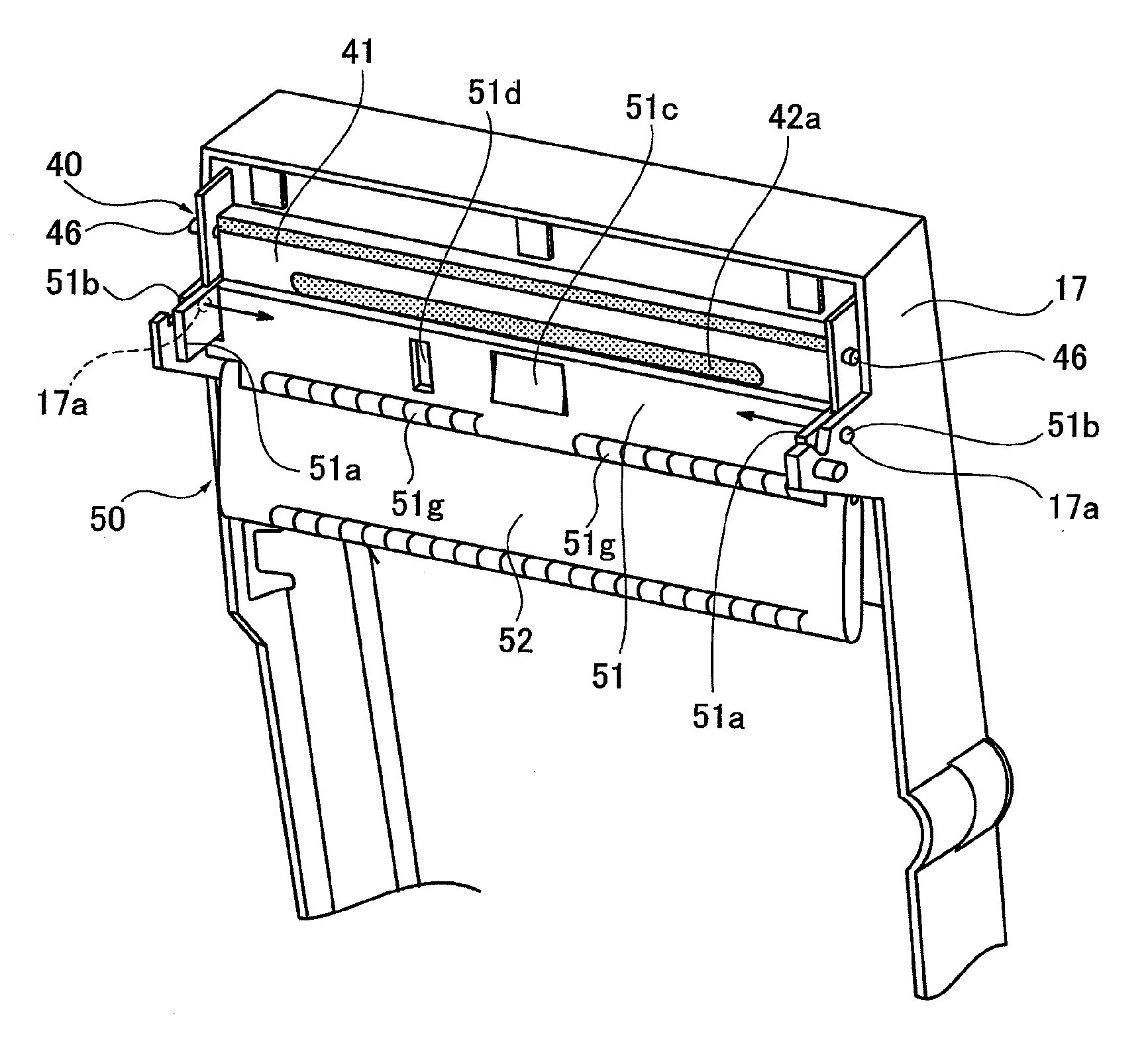
[0036]A thermal printer according to an embodiment of the present invention has a damper which is combined with a head cover disposed closest to a thermal printhead so that a distance from the damper and the thermal printhead is reduced and a paper container is disposed close to the thermal printhead so that an entire size of the thermal printer, especially a length in a front-back direction, that is, a paper feeding direction is reduced.

[0037]That is, the thermal printer according to an embodiment of the present invention has a configuration in which the damper to press a paper fed on a paper feeding path is combined with the head cover disposed on the paper feeding path and configured to partially cover the thermal printhead.

[0038]According to such a configuration of the thermal printer of an embodiment of the present invention, the head cover partially covering the thermal printhead is disposed closest to the thermal printhead.

[0039]Then, the damper is pressed on the paper fed on...


PUM


Abstract

A thermal printer includes a thermal printhead, a head cover configured to partially cover the thermal printhead, a paper container configured to house a paper, and a damper disposed on a paper feeding path between the thermal printhead and the paper container and configured to press the paper fed on the paper feeding path. The damper is combined with the head cover.

Description

CROSS REFERENCE TO RELATED APPLICATIONS[0001]The present application is based on and claims priority from Japanese Application Number 2010-27830, filed on Feb. 10, 2010, the disclosure of which is hereby incorporated by reference herein in its entirety.BACKGROUND OF THE INVENTION[0002]1. Field of the Invention[0003]The present invention relates to a thermal printer, more particularly, to an improvement of a damper to apply a tension to a paper (thermal paper) sent to a thermal printhead.[0004]2. Description of the Related Art[0005]In a thermal printer, a paper (thermal paper) contained in a paper container is fed to a position of a thermal printhead and then a thermal printing is performed by the thermal printhead. When printing is performed, the paper is required to be appropriately stretched by applying an appropriate tension to the paper.[0006]Therefore, the damper is provided on a paper feeding path between the paper container and the thermal printhead and the damper is pressed ...

Claims


Application Information

Patent Timeline
IPC IPC(8): B41J2/325
CPCB41J2/32B41J15/042B41J29/38B41J29/02B41J29/13B41J15/16
Inventor MATSUSHIMA, GENMORI, YASUYUKIMUKAIJIMA, KATSUTOSHI
Owner CITIZEN WATCH CO LTD
Why Eureka
Try Eureka