Power conversion apparatus

a power conversion and auxiliary equipment technology, applied in the direction of cooling/ventilation/heating modification, propulsion parts, vehicle components, etc., can solve the problems of disadvantageous manufacturing cost, poor maintainability of the power conversion apparatus b>9/b>, and insufficient rigidity of the case b>94/b>, so as to ensure the stability of installation, facilitate manufacturing, and ensure the effect of good maintainability of electronic components

Active Publication Date: 2011-08-11
DENSO CORP
View PDF31 Cites 23 Cited by
  • Summary
  • Abstract
  • Description
  • Claims
  • Application Information

AI Technical Summary

Benefits of technology

[0042]At least two of the bus bars may be partially molded with resin to form an integrated bus bar assembly. The frame may also include a plurality of bus bar fixing sections for fixing the bus bar assembly. At least two of the bus bar fixing sections are located closer to the terminal block than to the center of the frame. This ensures the stability in installing the bus bar assembly on the frame and also mounting the input/output terminals on the terminal block, thus assuring electric connections of the input/output terminals with external terminals.
[0043]The internal unit may be designed to have installed therei

Problems solved by technology

In this case, since the components are fixed directly to the case 94, they may fail due to thermal stress applied to them.
Accordingly, since the case 94 has to be provided with many sealing members, the power conversion apparatus 9 is disadvantageous in the manufacturing cost.
In addition, the maintainability of the power conversion apparatus 9 is not good enough in this case, because both the bottom lid 941 and the top lid 942 have to be removed for maintenance work.
However, in this case, the maintainability and rigidity of the case 94 may become worse.
Further, since vibration o

Method used


Image

  • Power conversion apparatus
  • Power conversion apparatus
  • Power conversion apparatus

Examples


second embodiment

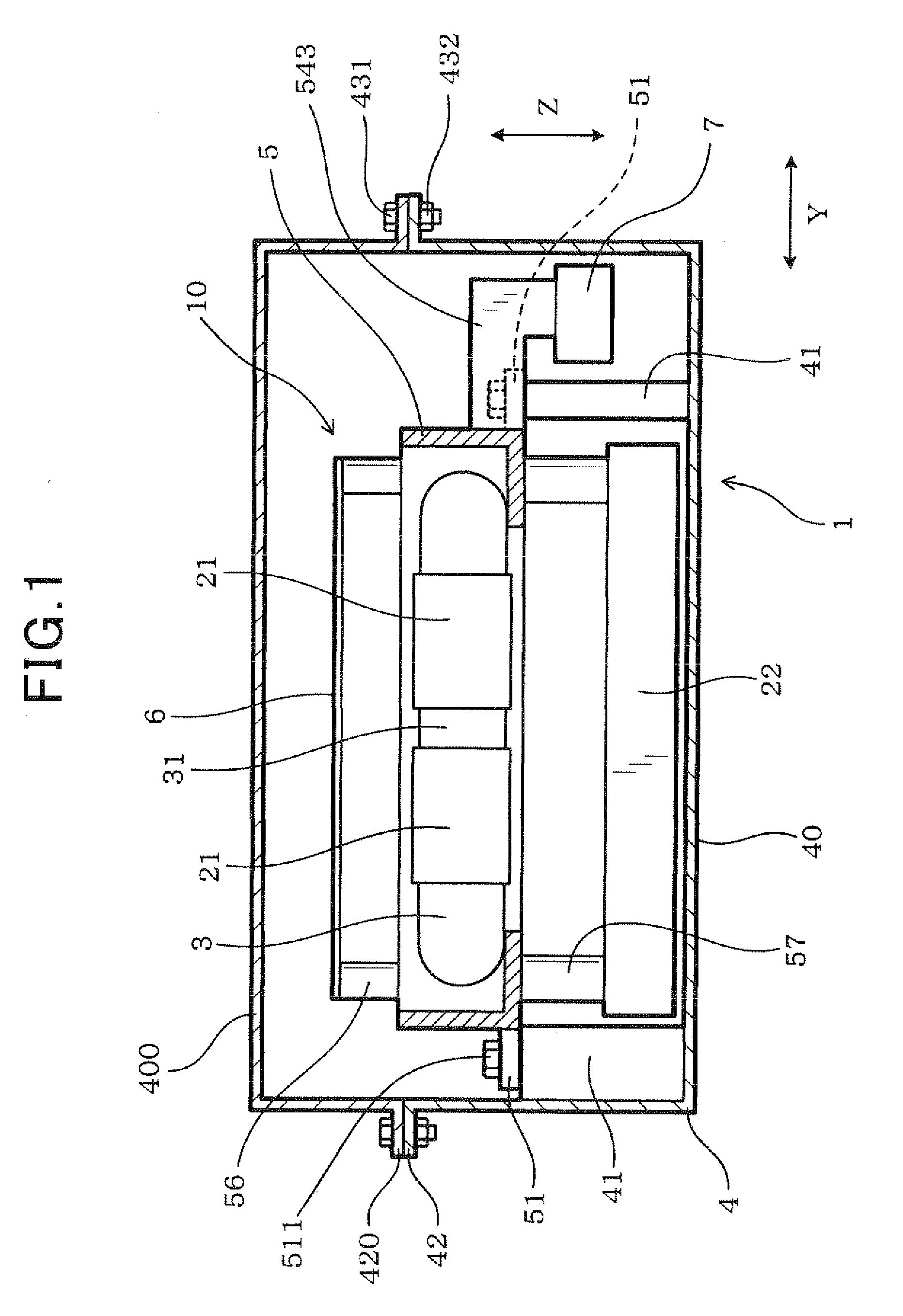
[0143]Next, a second embodiment of the invention will be described with reference to FIGS. 20 to 26. In the second embodiment, a wire holding section 59 for holding a conductive wire 15 is additionally provided in the frame 5 of the power conversion apparatus 1. At least one end of the conductive wire 15 is disposed within the case 4. In this embodiment, the conductive wire 15 connects the capacitor 22 with the control circuit board 6 within the case 4, so that the voltage across the capacitor 22 can be sent to the control circuit board 6 through the conductive wire 15 as a voltage signal indicative of the input voltage of the power conversion apparatus 1. The conductive wire 15 is covered with resin except both ends thereof, and has flexibility. The conductive wire 15 is laid outside the frame 5 to make a connection between the control circuit board 6 and the capacitor 22.

[0144]The wire holding section 59 has a hook-like shape as viewed from the height direction Z in FIGS. 21, 23, ...


PUM


Abstract

An electric power conversion apparatus is provided which includes electronic components, a cooler, an internal unit, a capacitor, and a case. The internal unit has a frame to which at least one of the electronic components and the cooler are secured and which surrounds all around the one of the electronic components. The frame includes unit fixing sections through which the internal unit is fixed to the case and capacitor fixing sections through which the capacitor is fixed to the internal unit. The capacitor fixing sections are located inward of the frame more than the unit fixing sections. The internal unit is fixed to the case and thus works as a beam to increase the mechanical rigidity of the case. The fixing of the internal unit to the case minimizes external force to be exerted through the case on the electronic component and the cooler.

Description

CROSS REFERENCE TO RELATED DOCUMENT[0001]The present application claims benefits of priority of Japanese Patent Application No. 2010-244597 filed on Oct. 29, 2010 and Japanese Patent Application No. 2010-24557 filed on Feb. 5, 2010, the disclosures of which are incorporated herein by reference.BACKGROUND OF THE INVENTION[0002]1. Technical Field of the Invention[0003]The present invention relates generally to a power conversion apparatus in which electronic components constituting a power conversion circuit and a cooler for cooling at least some of the electronic components are disposed in a case.[0004]2. Background Art[0005]An electric vehicle or a hybrid vehicle is equipped with a power conversion apparatus such as an inverter or a converter to convert source power into driving power for a drive motor. As shown in FIG. 27, such a power conversion apparatus 9 includes various electronic components including semiconductor modules 921 each incorporating therein switching elements, and...

Claims


Application Information

Patent Timeline
IPC IPC(8): H05K7/20
CPCB60K2001/005H05K7/20927H02M7/003
Inventor NAKASAKA, AKIRANODA, SATOSHIOOHAMA, KENICHI
Owner DENSO CORP
Why Eureka
Try Eureka