Decoration panel

a technology of decoration panel and light guide, which is applied in the direction of planar/plate-like light guide, lighting and heating apparatus, instruments, etc., can solve the problems of difficult to see painted colors and printed patterns, and unfavorable increase the thickness of the decoration panel, so as to reduce the volume of the decoration panel and achieve uniform illumination effect. , the effect of thinning the volum

Active Publication Date: 2011-08-11
COMPAL ELECTRONICS INC
View PDF6 Cites 17 Cited by
  • Summary
  • Abstract
  • Description
  • Claims
  • Application Information

AI Technical Summary

Benefits of technology

[0009]The invention is further directed to a decoration panel capable of illuminating which has simple elements and compacted volume.
[0028]In light of the foregoing, a plurality of diffusing particles is distributed in the light guide so that the decoration panel of the invention can have substantially evenly illuminating effect. In addition, merely the light shielding pattern layer is disposed on the light guide can the illuminating patterns be shown so as to reduce the volume of the decoration panel. Accordingly, the decoration panel of the invention is capable of illuminating and further has a thinned volume and a simple design.

Problems solved by technology

However, the painted colors and the printed patterns are difficultly seen if the ambient light is weak.
However, the backlight module of a display includes a plurality of optical plates or optical films for providing desirable display light source, which unfavorably increases the thickness of the decoration panel.

Method used


Image

  • Decoration panel
  • Decoration panel
  • Decoration panel

Examples


first embodiment

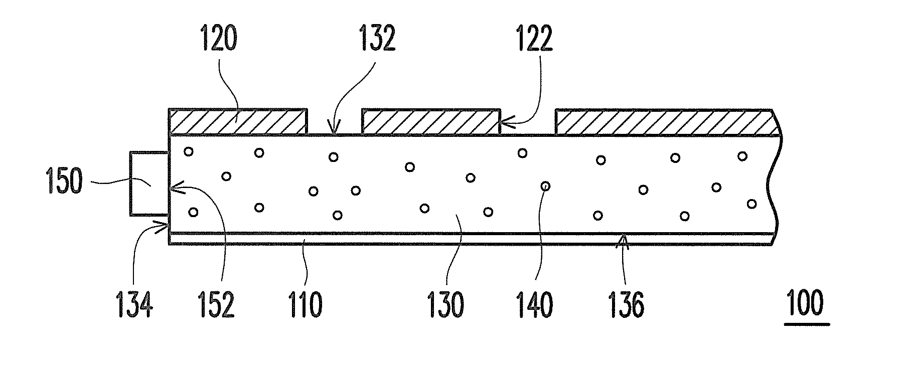
[0041]FIG. 1 schematically illustrates a cross-sectional view of a decoration panel according to the invention. Referring to FIG. 1, a decoration panel 100 includes a reflective layer 110, a light shielding pattern layer 120, a light guide 130, a plurality of diffusing particles 140, and a light emitting device 150. The light shielding pattern layer 120 is opposite to the reflective layer 110 and has a plurality of openings 122. The light guide 130 is disposed between the reflective layer 110 and the light shielding pattern layer 120. The plurality of diffusing particles 140 is distributed within the light guide 130. The light guide 130 has a light-exiting surface 132, a side surface 134, and a reflective surface 136. The light emitting device 150 is disposed beside the side surface 134 of the light guide 130 and the reflective layer 110 is disposed on the reflective surface 136 of the light guide 130 for reflecting the light to the light-exiting surface 132. In the present embodime...

third embodiment

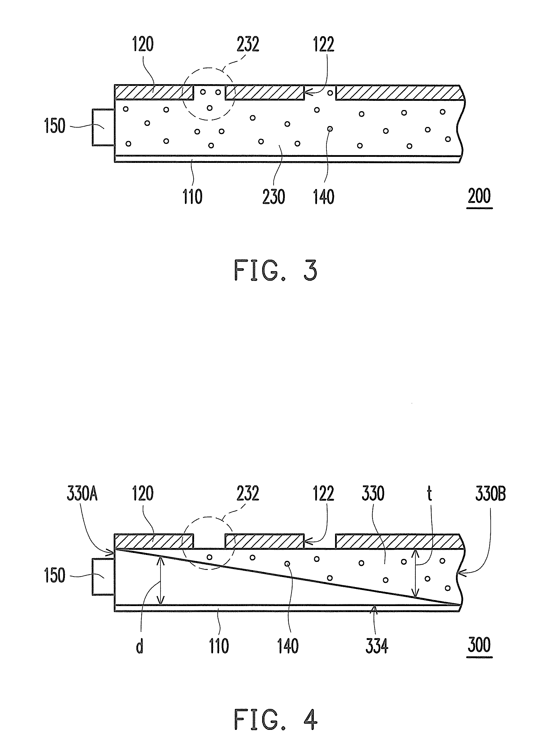
[0054]In addition, in the present embodiment, a thickness t of the light guide 430 is gradually decreased from a first side 430A of the light guide 430 adjacent to the light emitting device 150 toward a second side 430B opposite to the first side 430A. Furthermore, a distance d from the reflective layer 110 to the light guide 430 is, on the contrary, gradually increased with the decrease of the thickness t of the light guide 430. Similar to the third embodiment, the wedge-shaped light guide 430 conduces to change the transmission direction of the light beam emitted from the light emitting device 150. Therefore, the decoration panel 400 can have even brightness represented in different openings 122 without disposing any additional diffusing element therein. In specific, the wedge-shaped light guide 430 can have a substantially flat reflective surface (not marked) facing to the reflective layer 110 and no diffusing structure or diffusing pattern is required to be disposed on the subst...

seventh embodiment

[0062]FIG. 8 schematically illustrates a cross-sectional view of a decoration panel according to the invention. Referring to FIG. 8, the decoration panel 700 includes a light guide 710, a plurality of diffusing particles 720, a reflective layer 730, and a light emitting device 740. The light guide 710 includes a first portion 712 and a second portion 714 connected to the first portion 712. The diffusing particles 720 are distributed within the second portion 714 of the light guide 710. The reflective layer 730 is disposed at a side of the first portion 712 away from the second portion 714. The light emitting device 740 is disposed beside the first portion 712 of the light guiding plate 710 and the light emitting device 740 can be a light bar, a lamp, or a cold cathode lamp.

[0063]In the present embodiment, the light emitting device 740 is used for providing light to achieve the illumination of the decoration panel 700. Therefore, the light beam emitted from the light emitting device ...


PUM


Abstract

A light guide module capable of illuminating and being applied in a device for decoration is provided. The light guide module includes a reflective layer, a light guide with a plurality of diffusing particles, and a light source. The light guide has a side surface, a reflective surface and a light-exiting surface, thereby allowing a light from the light source to enter and reflect and exit the light guide respectively. The reflective layer is disposed on the reflective surface of the light guide for reflecting the light to the light-exiting surface. The light guide forms a portion of an outer surface of the device.

Description

CROSS-REFERENCE TO RELATED APPLICATION[0001]This application claims the priority benefit of U.S. provisional application Ser. No. 61 / 303,319, filed on Feb. 11, 2010. The entirety of the above-mentioned patent application is hereby incorporated by reference herein and made a part of this specification.BACKGROUND OF THE INVENTION[0002]1. Field of the Invention[0003]The invention generally relates to a light guide module, in particular, to a light guide module serving as a decoration panel.[0004]2. Description of Related Art[0005]A product usually has an outer surface which can be formed by a decoration panel so as to provide required visual effects such as a pattern design, a logo presentation, and the like. Conventionally, the decoration panel can be painted with specific colors or printed with the required patterns or logo for achieving the required visual effect such as showing the logo. However, the painted colors and the printed patterns are difficultly seen if the ambient light ...

Claims


Application Information

Patent Timeline
Patent Type & Authority Applications(United States)
IPC IPC(8): F21V7/22
CPCG02B6/0041G09F13/18G02B6/006G02B6/0046
Inventor CHEN, YIN-TAFAN, KUANG-CHENGLI, SHIH-WEI
Owner COMPAL ELECTRONICS INC
Why Eureka
Try Eureka