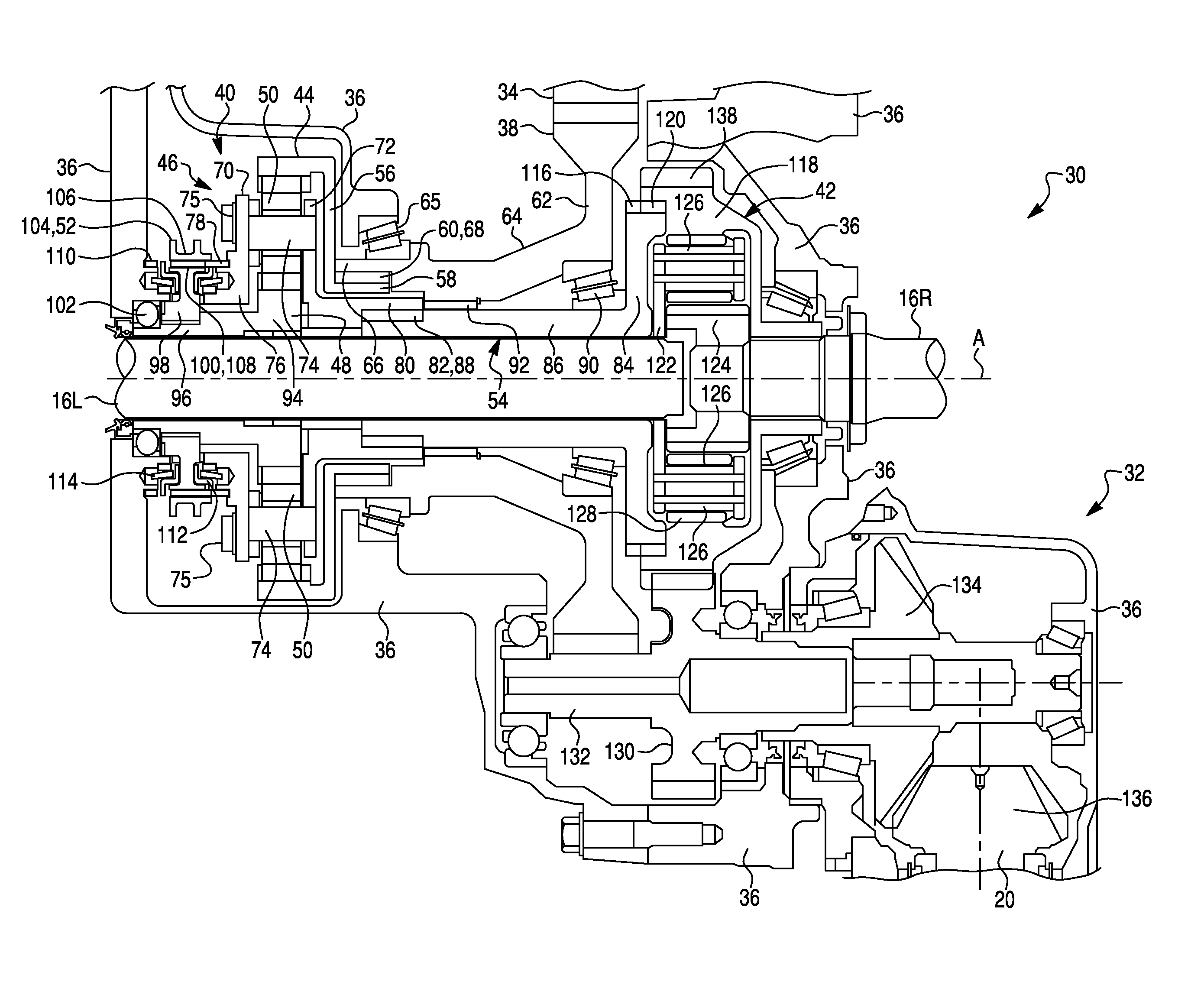
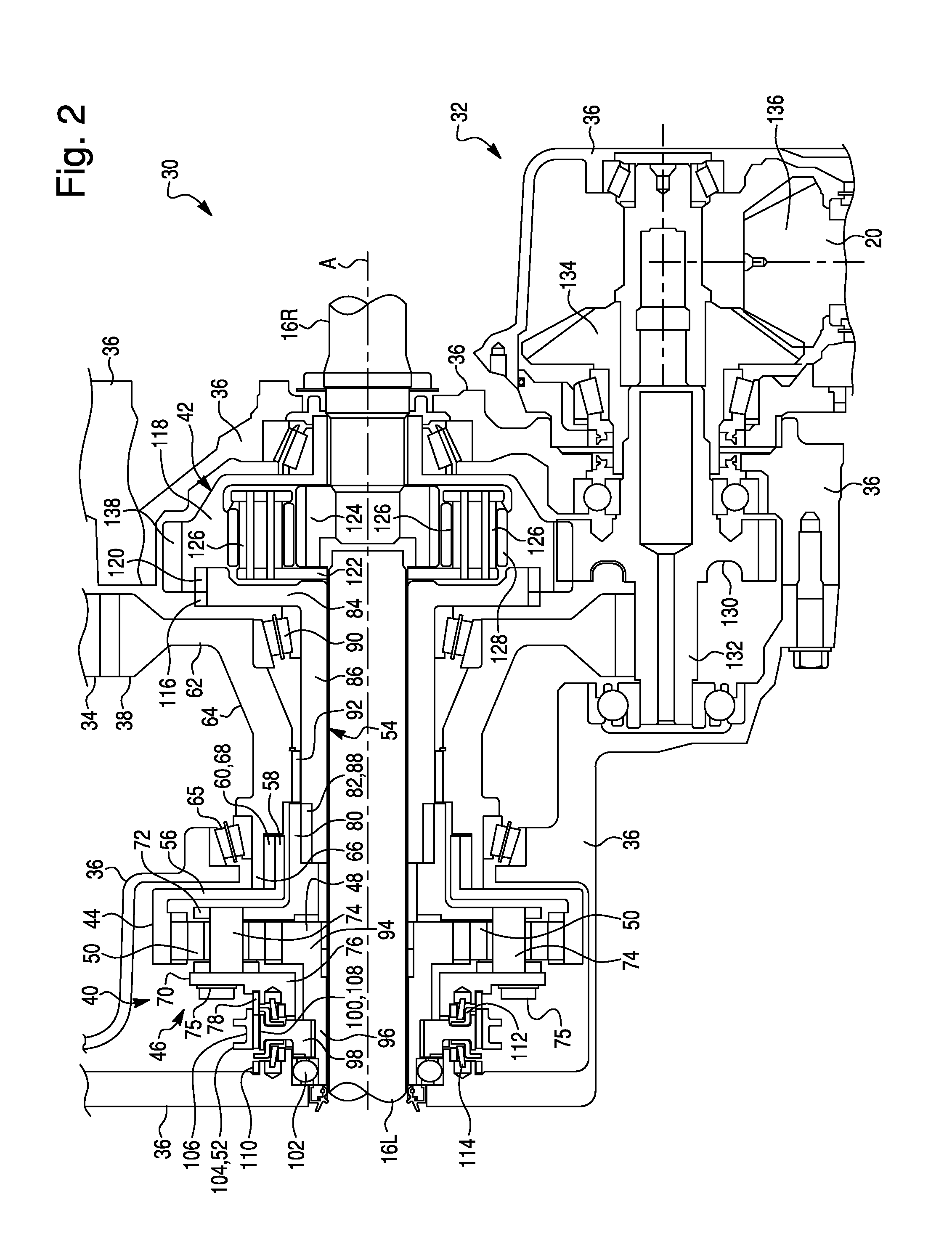
[0011]According to one aspect of the disclosure a transaxle for driving at least a pair of wheels of a vehicle that are spaced apart in a transverse direction relative to the vehicle can include a housing, a low range gear assembly, and a differential gear assembly. The low range gear assembly can be mounted in the housing and can include a ring gear, a carrier, a plurality of planet gears, a sun gear, and a clutch. The ring gear, the carrier, and the sun gear can be mounted in the housing to rotate about an axis parallel to the transverse direction. The plurality of planet gears can be rotatably mounted on the carrier and can engage the ring gear. The sun gear can engage the plurality of planet gears. The clutch can be mounted in the housing. The clutch can be selectively movable between a first position where the clutch engages each of the sun gear and the carrier and permits rotation of the sun gear relative to the housing and a second position where the clutch engages each of the sun gear and the housing and rotationally fixes the sun gear relative to the housing. The differential gear assembly can be mounted in the housing and can permit one of the pair of wheels to rotate relative to the other of the pair of wheels. The differential gear assembly can include an input member, first and second output structures, and first and second driveshafts. The input member and the first and second driveshafts can be mounted in the housing to rotate about the axis. The input member can be driven by the carrier. The first and second output structures can each be connected to and driven by the input member. The first driveshaft can be connected to the first output structure and a first one of the pair of wheels and can pass through each of the sun ring gear, the carrier, and the sun gear. The second driveshaft can be connected to the second output structure and a second one of the pair of wheels.
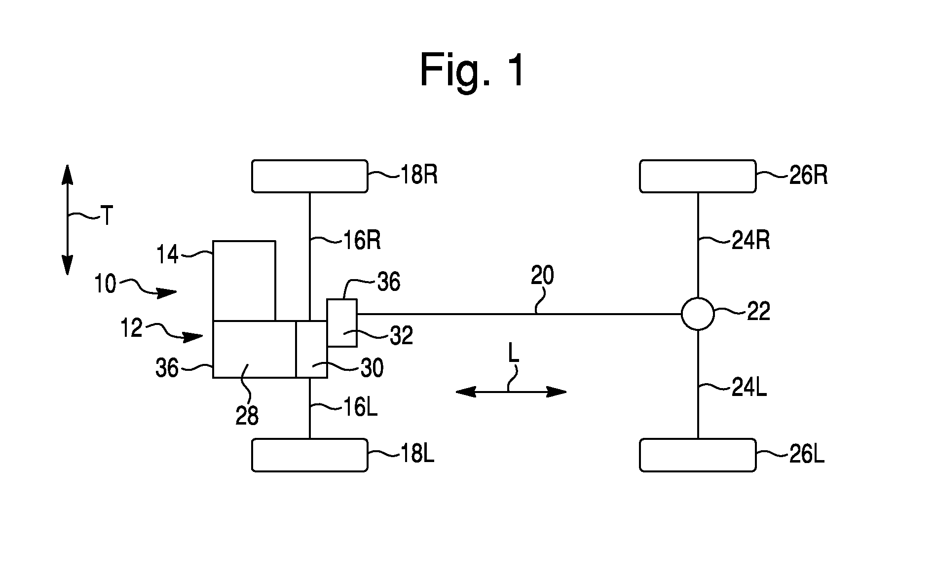
[0012]According to an aspect of the disclosed subject matter, a powertrain assembly for a vehicle can include a front pair of wheels, a rear pair of wheels, an internal combustion engine, a multi-ratio transmission, a final drive gear, a low range gear assembly, a front differential gear assembly, a power take-off assembly, a rear differential assembly, and first and second rear driveshafts. The front pair of wheels can be spaced apart in a transverse direction relative to the vehicle. The rear pair of wheels can be spaced apart in the transverse direction and can be spaced from the front pair of wheels in a longitudinal direction relative to the vehicle. The internal combustion engine can be aligned parallel to the transverse direction and can be mounted to the vehicle intermediate each wheel of the front pair of wheels. The multi-ratio transmission can be aligned parallel to the transverse direction, can be mounted to the vehicle intermediate each wheel of the front pair of wheels and can be driven by the engine. The multi-ratio transmission can include a plurality of forward drive ratios, a reverse drive ratio, and an output gear. The output gear can rotate about an output axis parallel to the transverse direction. The final drive gear can be mounted in the housing for rotation about the axis and can engage and can be driven by the output gear. The low range gear assembly can include a ring gear, a carrier, a plurality of planet gears, a sun gear, a clutch, and an output member. The ring gear can be mounted in the housing to rotate about an axis parallel to the transverse direction and can be connected to and driven by the final drive gear. The carrier can be mounted in the housing to rotate about the axis. The plurality of planet gears can be rotatably mounted on the carrier and can engage the ring gear. The sun gear can be mounted in the housing to rotate about the axis and can engage the plurality of planet gears. The clutch can be mounted in the housing. The clutch can be selectively movable between a first position where the clutch engages each of the sun gear and the carrier and permits rotation of the sun gear relative to the housing and a second position where the clutch engages each of the sun gear and the housing and rotationally fixes the sun gear relative to the housing. The output member can be connected to the carrier and driven by the carrier at one of a high range final drive ratio and a low range final drive ratio that is less than the high range final drive ratio. The high range final drive ratio can be determined by the output gear, the final drive gear, and the first position of the clutch and can be independent of each of the plurality of forward drive ratios and the reverse drive ratio. The low range final drive ratio can be determined by the output gear, the final drive gear, and the second position of the clutch and can be independent of each of the plurality of forward drive ratios and the reverse drive ratio. The front differential gear assembly can include an input member, first and second output structures, first and second driveshafts, and a third output structure. The input member can be mounted in the housing to rotate about the axis and can be driven by the output member. Each of the first output structure and a second output structure can be connected to and driven by the input member. The first driveshaft can be mounted in the housing to rotate about the axis, can be connected to the first output structure and a first one of the pair of wheels, and can pass through each of the sun ring gear, the carrier, and the sun gear. The second driveshaft can be mounted in the housing to rotate about the axis and can be connected to the second output structure and a second one of the pair of wheels. The power take-off gear assembly can include a crown gear, a pinion gear, and a propeller shaft. The crown gear can be driven by the third output structure to rotate about an axis parallel to the transverse direction. The pinion gear can engage the crown gear and can rotate about an axis parallel to the longitudinal direction. The propeller shaft can be driven by the pinion gear and can extending along an axis parallel to the longitudinal direction. The rear differential gear assembly can be driven by the propeller shaft. The first rear driveshaft can be connected to and driven by the rear differential gear assembly and can be connected to and drive a first one of the rear pair of wheels. The second rear driveshaft can be connected to and driven by the rear differential gear assembly and can be connected to and drive a second one of the rear pair of wheels.

