Modular Joint Prosthesis
- Summary
- Abstract
- Description
- Claims
- Application Information
AI Technical Summary
Benefits of technology
Problems solved by technology
Method used
Image
Examples
example 1
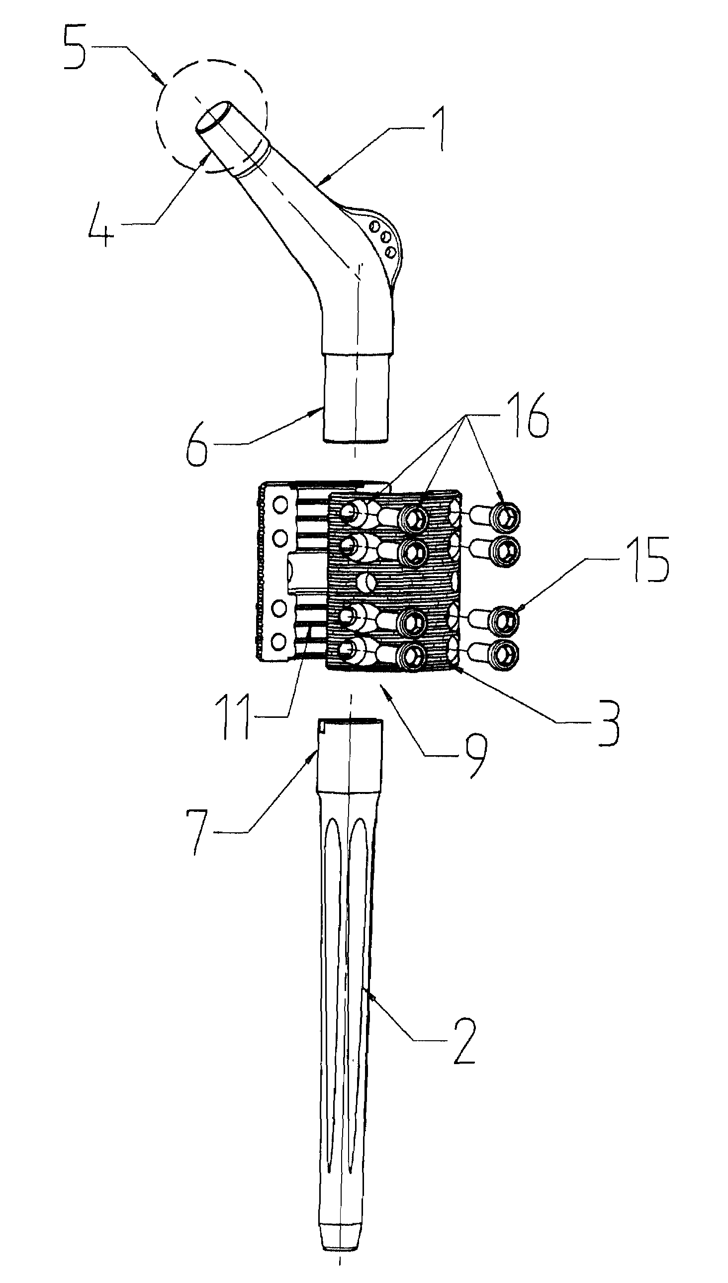
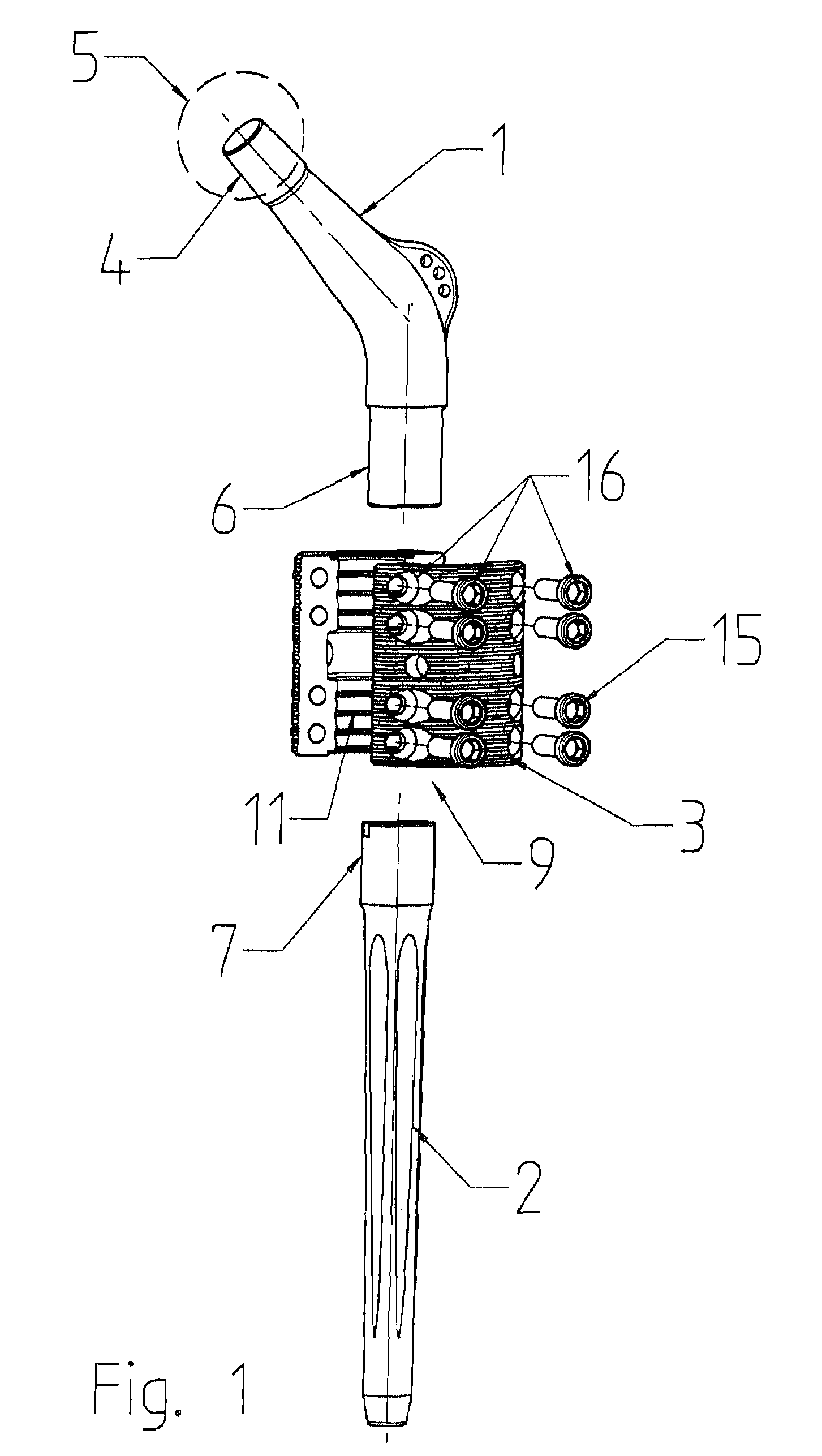
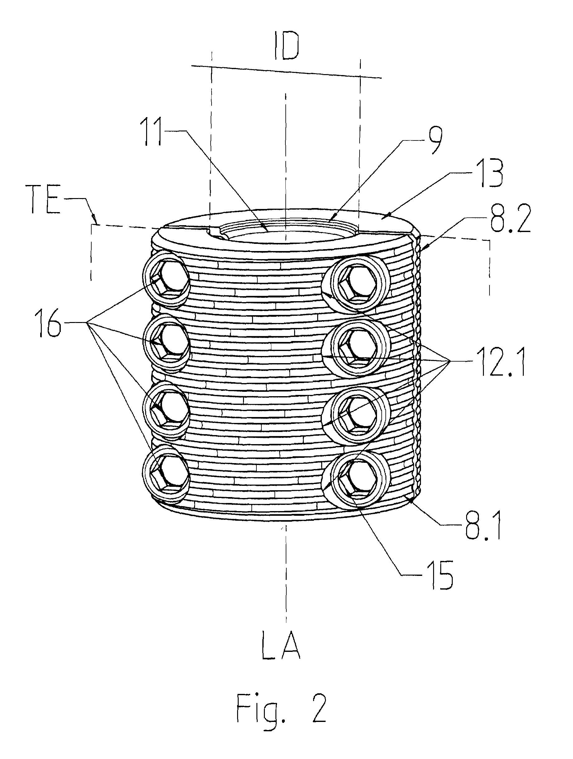
[0035]FIG. 1 shows the basic structure of the joint prosthesis according to the invention in a first embodiment variant in an exploded illustration. The joint prosthesis according to the invention which is used, for example, in case of resections due to metastases in the bone, hip revisions or also in case of infections or trauma, is composed of a curved, one-piece head part 1 which is adapted according to the biomechanical conditions of the anatomy of the respective patient, a nail 2, for example femur nail, and a connection module 3. On the conical pin 4 of the head part 1, a slip-on joint ball 5 is arranged which engages with a non-illustrated joint socket. The distal end of the head part 1 is formed into a cylindrical shaft 6 from solid metal and is inserted into the connection module 3, which is described later, to be fastened therein.
[0036]The nail 2 is inserted into the bone marrow canal of the non-illustrated long bone and anchored therein. The nails 2 have different lengths...
example 2
[0045]FIG. 6 shows a further variant of the joint prosthesis according to the invention in an exploded illustration. This joint prosthesis comprises a shaft-like neck piece 19 of relatively short length and a nail 2, for example femur nail. The essence of this variant of the invention is that the connection module 3, which in example 1 is still a separate part, becomes an integral part of the shaft-like neck piece 19 so that a total of only two elements form the joint prosthesis according to the invention.
[0046]As in example 1, the neck piece 19 has a conical pin 4 onto which a slip-on joint ball 5 is arranged which engages with a non-illustrated joint socket. The distal end of the neck piece 19 is formed into a helmet-like receiving head 20 which has an insertion opening 21 for inserting the nail neck 7. The receiving head 20 is provided with a slot 23 which runs in the direction of the longitudinal axis LA of the head part 19 approximately as far as into the shaft 22 of the neck p...
PUM
 Abstract
Description
Claims
Application Information
 - R&D
- Intellectual Property
- Life Sciences
- Materials
- Tech Scout
- Unparalleled Data Quality
- Higher Quality Content
- 60% Fewer Hallucinations
Browse by: Latest US Patents, China's latest patents, Technical Efficacy Thesaurus, Application Domain, Technology Topic, Popular Technical Reports.
© 2025 PatSnap. All rights reserved.Legal|Privacy policy|Modern Slavery Act Transparency Statement|Sitemap|About US| Contact US: help@patsnap.com


