
Control device for hydraulic transmission vehicle

a technology of control device and transmission vehicle, which is applied in the direction of machines/engines, positive displacement liquid engines, instruments, etc., can solve the problems of vehicle speed limit varying back and forth, insufficient horsepower may not be available,

Active Publication Date: 2011-08-11
KOMATSU LTD
View PDF16 Cites 39 Cited by
  • Summary
  • Abstract
  • Description
  • Claims
  • Application Information

AI Technical Summary

Benefits of technology

The present invention relates to a control device for a hydrostatic transmission vehicle that can constantly execute stable works while inhibiting the variation in the matching engine speed due to the load pressure in the hydraulic transmission. The control device includes a vehicle speed setting section, a hydraulic sensor, a torque limit setting section, a vehicle speed limit setting section, a vehicle speed selection section, and a pump and motor displacement control section. By setting the vehicle speed based on both the forward / rearward travel command and the gear stage command, and controlling the displacement of the pump and motor hydraulic motor based on the selected vehicle speed, the control device can keep the engine speed constant and match the torque limit of the hydraulic transmission, even when the pressure under load varies. This results in a reduction in noises in operations and fuel consumption.

Problems solved by technology

Simply put, a sufficient horsepower may not be available.
In executing the above control, however, the vehicle speed limit varies back and forth between minimum and maximum in the motor range even when the pressure slightly varies.

Method used


Image

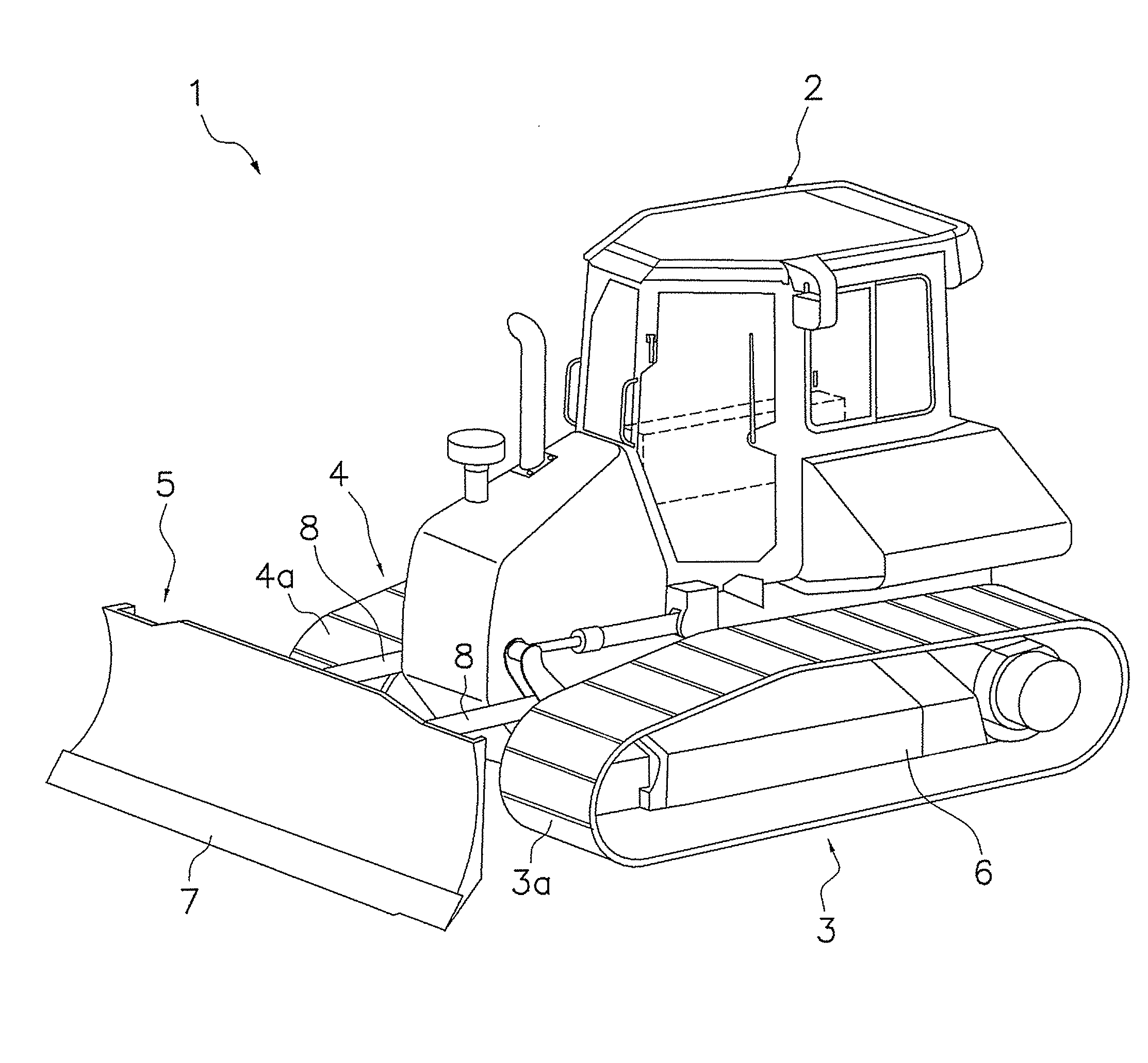
  • Control device for hydraulic transmission vehicle
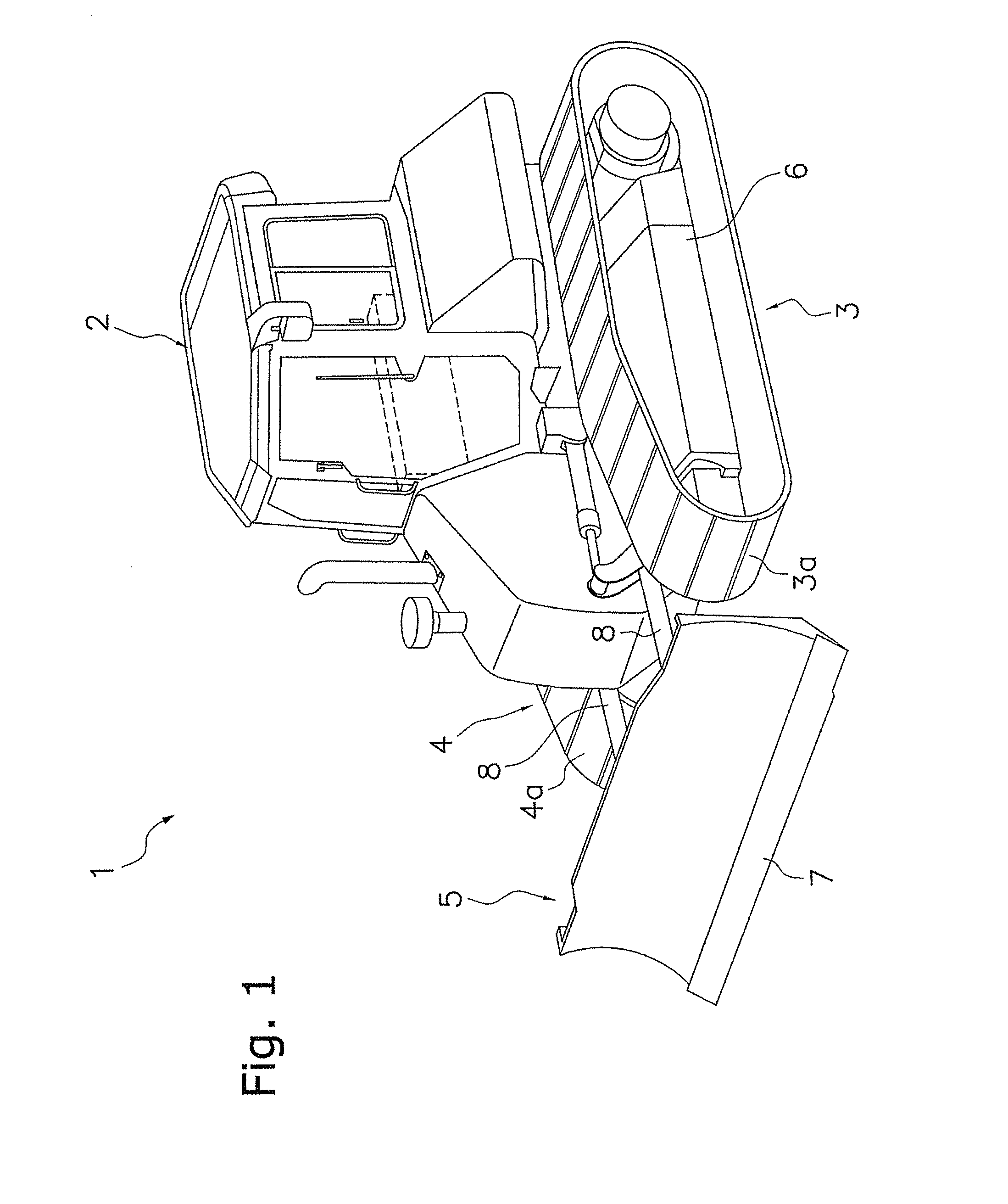
  • Control device for hydraulic transmission vehicle
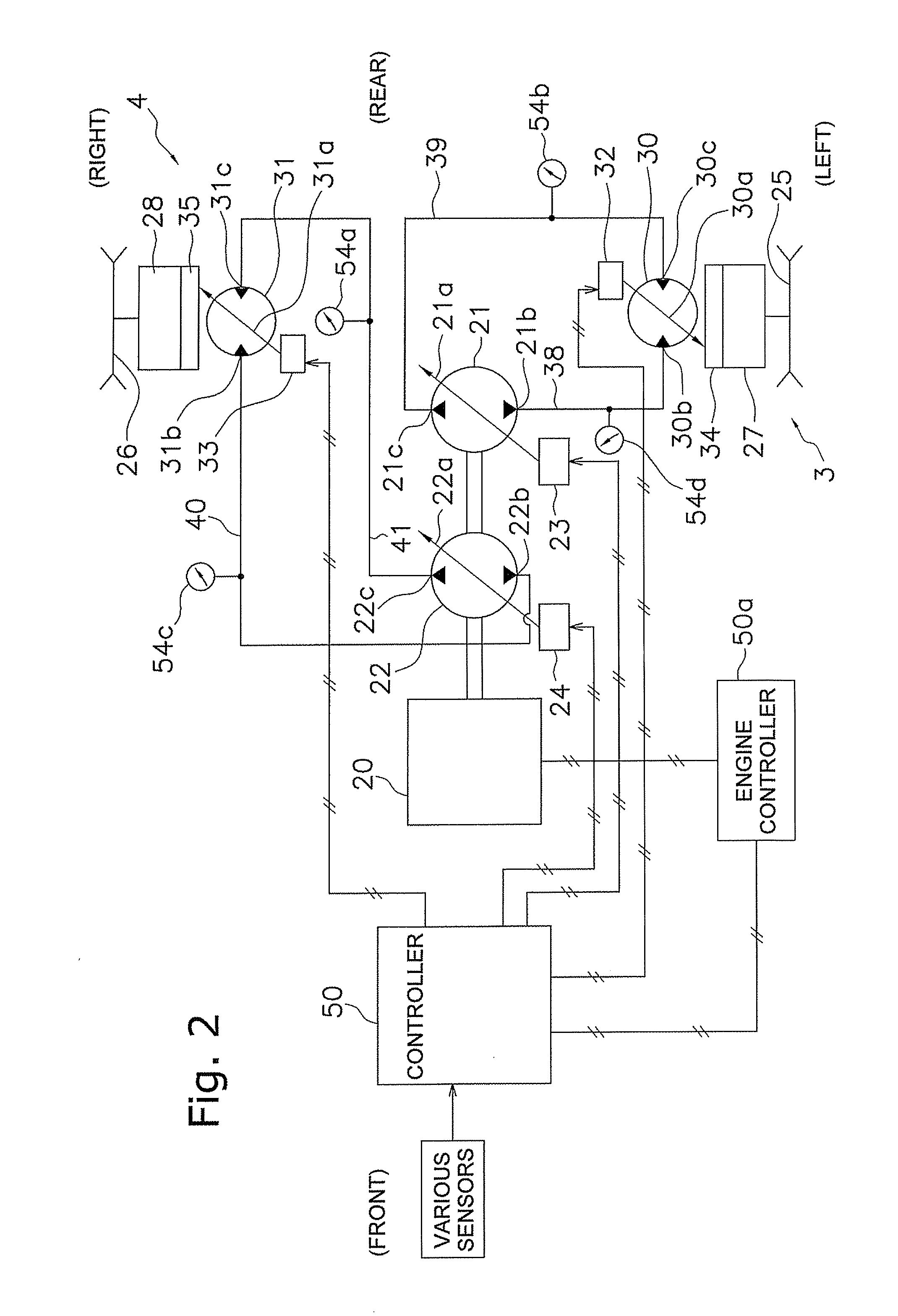
  • Control device for hydraulic transmission vehicle

Examples


first exemplary embodiment

Features of First Exemplary Embodiment

[0117](1) Even if instructed to be operated at the high idle engine speed by an operator, the bulldozer is automatically operated at the predetermined partial engine speed by the low rotation matching processing when the commanded vehicle speed is in the preliminarily set low and intermediate speed range. Therefore, reduction in fuel consumption and reduction in noises can be achieved without making an operator execute bothersome operations such as switching of operation modes.

[0118]Further, both the pump displacement and the motor displacement are set for achieving the set vehicle speed when the engine is rotated at the partial engine speed in the low and intermediate speed range. Therefore, the vehicle speed can reach the operator's desired vehicle speed even when the engine speed is low.

[0119](2) In executing the low rotation matching processing, the engine speed is controlled and increased to the high idle engine speed when the commanded veh...

second exemplary embodiment

Features of Second Exemplary Embodiment

[0129]According to the present exemplary embodiment, advantageous effects similar to those of the first exemplary embodiment can be achieved without changing the pump and motor displacement control section of the well-known type.

[0130]Further, a plurality of maps is not herein required. Therefore, it is possible to easily cope with even such a case that the partial engine speed is required to be changed.

Control Blocks

Third Exemplary Embodiment

[0131]FIG. 15 illustrates a control block diagram of a controller 50″ of the present vehicle according to a third exemplary embodiment of the present invention. It should be noted that only the differences from the first and second exemplary embodiments will be hereinafter described. The same reference numerals will be assigned to the same components as those of the first and second exemplary embodiments, and explanation thereof will be hereinafter omitted.

[0132]In the third exemplary embodiment, the set v...

third exemplary embodiment

Features of Third Exemplary Embodiment

[0144]According to the present exemplary embodiment, advantageous effects similar to those of the first exemplary embodiment can be achieved without changing the pump and motor displacement control section of the well-known type.

[0145]Further, the motor displacement is set by the PID control in setting the motor displacement for avoiding lack of power in working of the bulldozer. It is thereby possible to accurately and reliably set the motor displacement to be a desired displacement

[0146]Yet further, the motor displacement is determined by the PID control. It is thereby possible to further reliably prevent occurrence of the hunting phenomenon than the first and second exemplary embodiments.

Other Exemplary Embodiments

[0147](a) In the vehicle speed limit setting section 76, the pressure is set to be reduced in proportion to increase in the vehicle speed limit in the range that the motor displacement is controlled. However, the pressure may be con...


PUM


Abstract

A control device controls a hydrostatic transmission vehicle having a hydrostatic transmission including a variable displacement pump and a variable displacement hydraulic motor. The control device is configured to set a set vehicle speed based on a forward / rearward travel command and a gear stage command instructed by an operator, to set a torque limit usable for the hydrostatic transmission based on an engine speed, to set a vehicle speed limit based on a pressure in the hydraulic circuit and the torque limit, to select a lower one of the set vehicle speed and the vehicle speed limit, and to control respective displacements of the variable displacement pump and the variable displacement hydraulic motor based on the selected vehicle speed.

Description

CROSS-REFERENCE TO RELATED APPLICATIONS[0001]This national phase application claims priority to Japanese Patent Application No. 2008-320893 filed on Dec. 17, 2008. The entire disclosure of Japanese Patent Application No. 2008-320893 is hereby incorporated herein by reference.TECHNICAL FIELD[0002]The present invention relates to a control device for a hydrostatic transmission vehicle, particularly to a control device for a hydrostatic transmission vehicle, typified by a bulldozer, which includes a variable displacement pump to be driven by an engine and a variable displacement hydraulic motor to be rotated by the pressurized oil from the variable displacement pump and is configured to be operated while the engine speed is set to be either a high idle engine speed or a given engine speed less than the high idle engine speed by an operation of a fuel regulation lever (or dial).BACKGROUND ART[0003]Some of the work vehicles, such as bulldozers, include a hydrostatic transmission (also he...

Claims


Application Information

Patent Timeline
Patent Type & Authority Applications(United States)
IPC IPC(8): F16H61/4008B62D11/02
CPCE02F9/202Y10T477/68F16H59/06F16H59/44F16H61/421F16H61/431F16H61/47F16H2059/6861F16H2059/366B60W10/06B60W10/11F16H59/46F16H61/0213F16H61/061F16H61/40F16H61/4008Y10T477/679E02F9/2253F04B49/24F17D1/08F04B27/08
Inventor ISHIBASHI, EIJIMUKAINO, MASAYUKIYAMAMOTO, SHIGERUONODERA, YOSHITAKAISHIHARA, TAKAO
Owner KOMATSU LTD
Learn More