Device orientation determination

a technology of orientation determination and device, which is applied in the direction of instruments, surveying, and wellbore/well accessories, etc., can solve the problems of inability to directly determine the relationship, the accuracy of the calibration of each magnetic field sensor, and the inability to detect the calibration accuracy of the magnetic field sensor

Active Publication Date: 2011-08-11
HALLIBURTON ENERGY SERVICES INC
View PDF3 Cites 17 Cited by
  • Summary
  • Abstract
  • Description
  • Claims
  • Application Information

AI Technical Summary

Problems solved by technology

However, when imaging a borehole near formations that contain iron-oxides with magnetic fields sufficient to override the Earth's magnetic field as it appears at the magnetometers, the acquired sensor data at that location may contain magnetic field readings that are corrupt, or completely missing.
For example, in a navigation log where the borehole tool did not rotate more than a quarter turn and/or did not change deviation by more than 90 degrees, it is very difficult to tell if the calibration of each magnetic field sensor is correct.
When magnetic field sensor data is missing or corrupt during portions of this time period, the

Method used


Image

  • Device orientation determination
  • Device orientation determination
  • Device orientation determination

Examples


Embodiment Construction

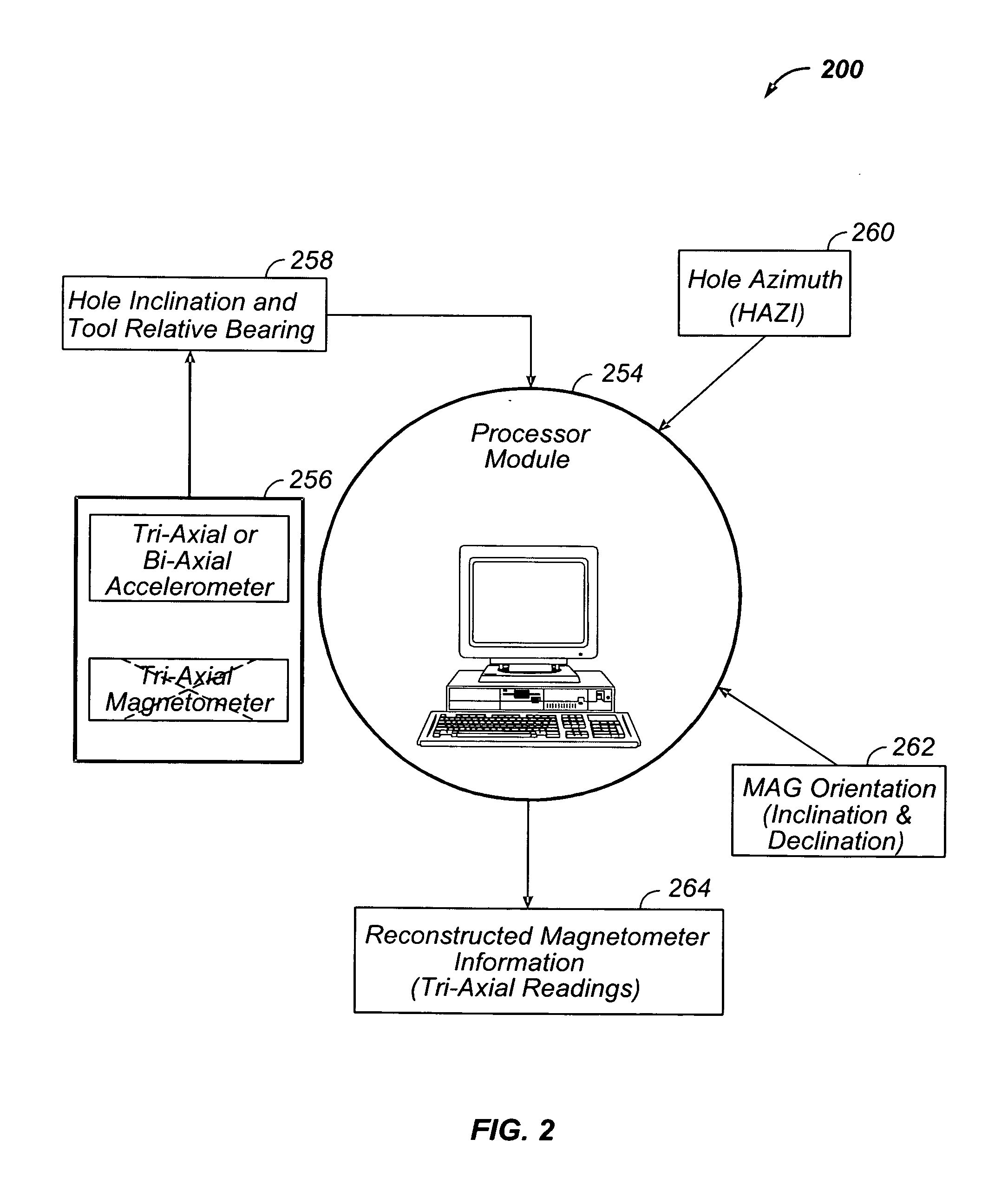
[0010]The various embodiments described herein operate to provide orientation information by deriving or reconstructing missing or corrupt magnetic field sensor data in various applications. These mechanisms can also be used to check valid magnetometer data for correct calibration. For example, in a navigation log where the borehole tool did not rotate more than a quarter turn and / or did not change deviation by more than 90 degrees, it is very difficult to tell if the calibration of each magnetic field sensor is correct. Using the embodiments disclosed, accelerometer data and a well survey can be used to generate comparison (reconstructed magnetic field sensor) data to assess the calibration of the actual magnetic field sensor data. The noise in the actual magnetic field sensor data can also be characterized and reduced using this comparison data.

[0011]A typical tri-axial magnetic field sensor suite contains three sensor units mounted orthogonal to each other; each one of the sensor...


PUM


Abstract

In some embodiments, apparatus and systems, as well as methods, may operate to obtain hole azimuth data or inclination data associated with a chassis (e.g., comprising a measurement or logging tool) in a borehole using interpolated data or survey data, and to determine magnetic field orientation of the chassis using a portion of the hole azimuth data, a portion of the inclination data, relative bearing data, and Earth magnetic field orientation data by reconstructing at least a portion of borehole magnetic field data that is corrupt or missing. Additional apparatus, systems, and methods are disclosed.

Description

BACKGROUND[0001]A variety of devices make use of magnetic sensors to orient themselves with respect to the Earth's Geographic Coordinates. More specifically, it is common to use a tri-axial magnetometer to measure the angle of the device with respect to the Earth's magnetic field, and a tri-axial accelerometer to measure the angle of the device with respect to the Earth's gravitational field. Together, these sensors can be used to estimate the device's pointing direction in magnetic bearing coordinates, unless the gravity and magnetic fields are either parallel or anti-parallel. Using a model of the Earth's magnetic field position, a correction estimate can be applied to re-reference the device from magnetic bearing coordinates to geographic coordinates, such as the Earth System of Coordinates.[0002]For example, one such device comprises a borehole imager that is configured to obtain images of a borehole drilled into the Earth. Six sensors (a tri-axial magnetometer and a tri-axial a...

Claims


Application Information

Patent Timeline
IPC IPC(8): G06F19/00
CPCG01V11/005
Inventor BONAVIDES, CLOVISTRACADAS, PHILIP WILLIAM
Owner HALLIBURTON ENERGY SERVICES INC
Why Eureka
Try Eureka