Method of Controlling a Combustor for a Gas Turbine

Active Publication Date: 2011-08-18
GENERAL ELECTRIC CO
View PDF27 Cites 27 Cited by
  • Summary
  • Abstract
  • Description
  • Claims
  • Application Information

AI Technical Summary

Problems solved by technology

While liquid fuel systems are desirable, either as a backup or alternate fueling system, their operating and maintenance costs are

Method used


Image

  • Method of Controlling a Combustor for a Gas Turbine
  • Method of Controlling a Combustor for a Gas Turbine
  • Method of Controlling a Combustor for a Gas Turbine

Examples


Embodiment Construction

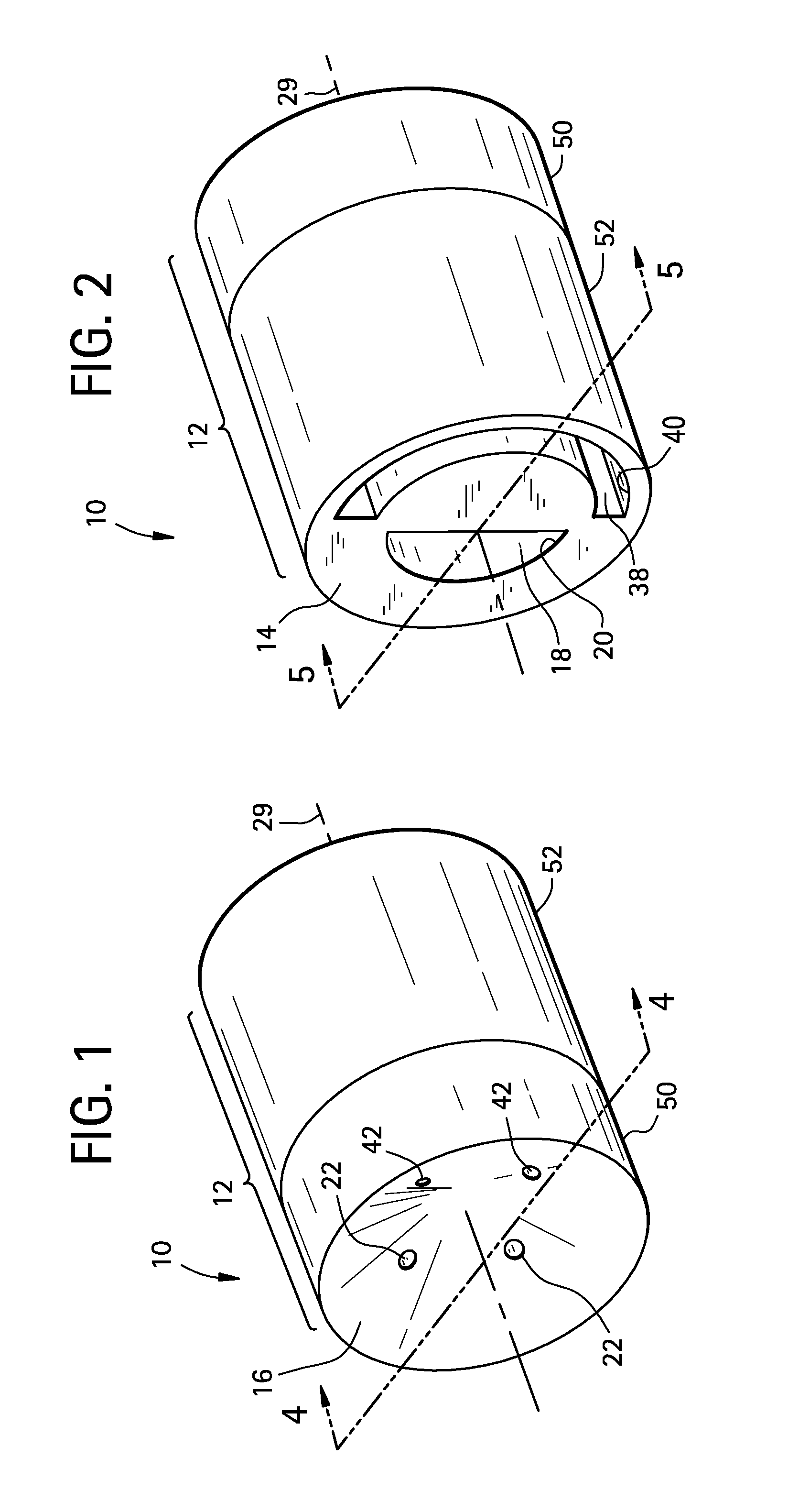
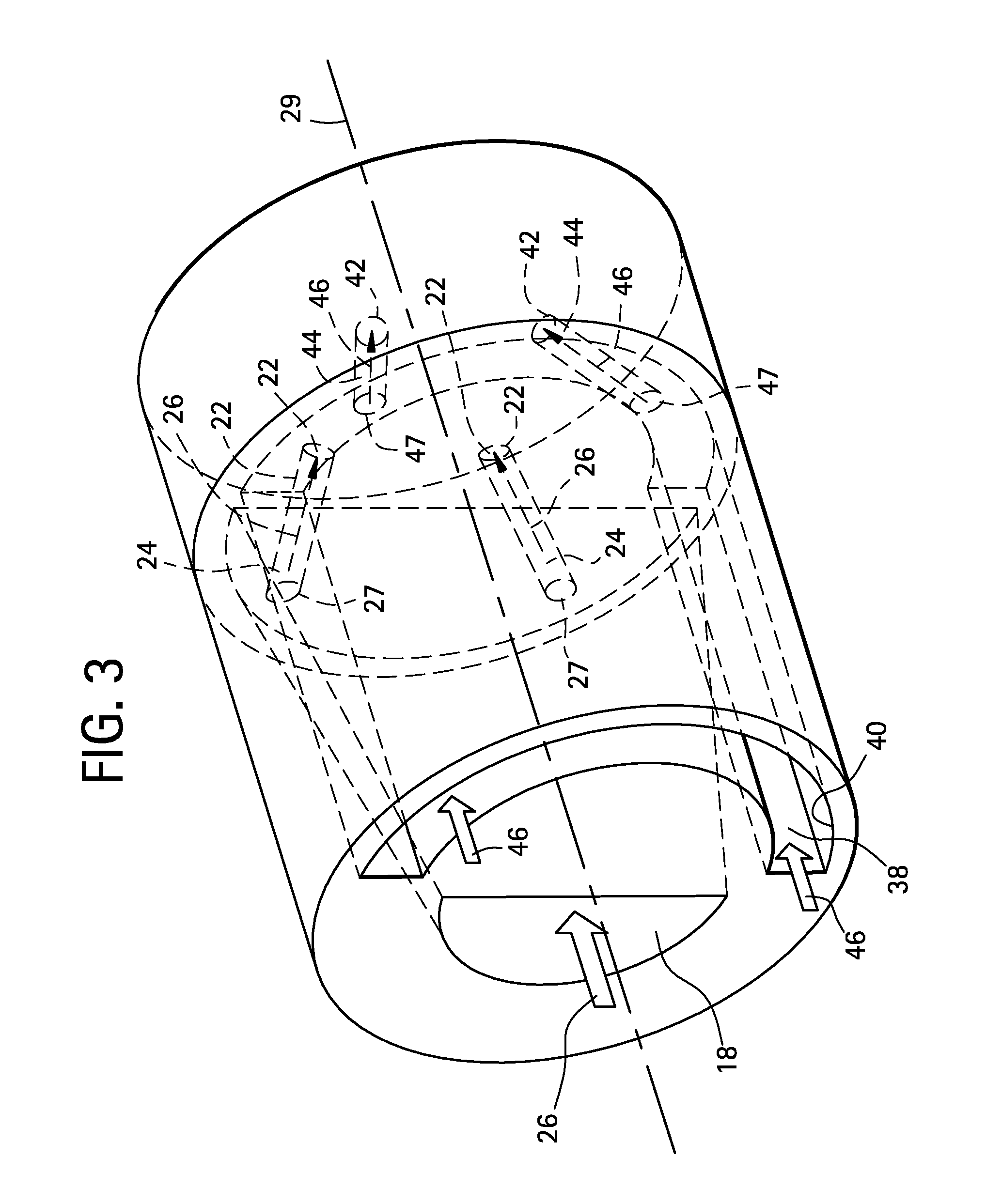
[0021]Referring to FIGS. 1-10, an exemplary embodiment of a fuel injector nozzle 10 is illustrated. Fuel injector nozzle 10 includes a nozzle body 12 that is configured for attachment to and fluid communication with a fuel cartridge or fuel injector 100 used in the combustor (not shown) of a gas turbine (not shown) to provide jets of liquid fuel, or jets of liquid fuel and another fluid, such as water, to atomize the fuel for combustion in the combustion chamber (not shown) of the combustor. Nozzle body 12 may have any suitable shape, including a right cylindrical shape as shown, and will generally have a shape that is configured for attachment to the fuel injector 100 to which it is joined (FIG. 6). Nozzle body 12 has an inlet end 14 and an opposed discharge or outlet end 16.

[0022]Nozzle body 12 also includes a fuel conduit 18 that extends from a fuel inlet 20 on inlet end 14 to a fuel outlet 22, or a plurality of fuel outlets 22, located on outlet end 16. Fuel outlet or outlets 22...


PUM


Abstract

A method of controlling a combustor of a gas turbine is disclosed. The method includes operatively disposing a combustor can in a combustor of a gas turbine. The combustor can comprising a plurality of combustor fuel nozzles, each having a fuel injector and configured to selectively provide a liquid fuel, a liquid fluid or liquid fuel and liquid fluid to a fuel injector nozzle that is configured to provide, respectively, a plurality of liquid fuel jets, a plurality of liquid fluid jets or a combination thereof, that are in turn configured to provide an atomized liquid fuel stream, an atomized liquid fluid stream, or an atomized and emulsified liquid fuel-liquid fluid stream, respectively. The method also includes selectively providing an amount of fuel, fluid or a combination thereof to the fuel injector nozzle to produce an atomized fuel stream, atomized fluid stream, or an atomized and emulsified fuel-fluid stream, respectively.

Description

BACKGROUND OF THE INVENTION[0001]Natural gas is, in many cases, the fuel of choice for firing gas turbines because of its lower cost and desirable combustion characteristics as compared with alternative fuels. Many combustion turbines, though, have the capability to fire either natural gas or a liquid fuel, including various grades of diesel fuel, such as No. 2 diesel fuel, depending on cost, availability and desired combustion characteristics. In many cases the liquid fuel system is used primarily as a backup system. As an example, current Dry Low NOX (DLN) combustors generally utilize a backup liquid fuel system. In other cases, gas turbine sites seasonally operate on liquid fuel due to the lower cost or enhanced availability of the liquid fuel.[0002]While liquid fuel systems are desirable, either as a backup or alternate fueling system, their operating and maintenance costs are currently prohibitive. Atomizing air is frequently used to provide atomization of the liquid fuel to ob...

Claims


Application Information

Patent Timeline
IPC IPC(8): F02C7/26F02C7/22
CPCF23D11/38F23R3/36F23L7/002
Inventor KHOSLA, SACHINLAL, MIHIRZEHENTBAUER, DANIEL SCOTT
Owner GENERAL ELECTRIC CO
Why Eureka
Try Eureka