Internal combustion engine controller

a technology of combustion engine controller and internal combustion engine, which is applied in the direction of electric control, charge feed system, fuel injection apparatus, etc., can solve the problems of low temperature of the intake piping and the temperature of the wall surface of the intake port, correspondingly large amount of unburned hc is discharged from the cylinder into the exhaust passage, and the negative pressure in the intake piping is not produced

Inactive Publication Date: 2011-08-18
TOYOTA JIDOSHA KK
View PDF11 Cites 26 Cited by
  • Summary
  • Abstract
  • Description
  • Claims
  • Application Information

AI Technical Summary

Benefits of technology

[0012]The invention provides a controller, with which it is possible to suppress discharge of unburned HC when an internal combustion engine is started.

Problems solved by technology

However, when the internal combustion engine is started, especially when the engine is cold-started, the temperature in the intake piping and the temperature of the wall surface of the intake port are low and the negative pressure in the intake piping is not produced yet.
However, when a large amount of fuel is supplied, a correspondingly large amount of unburned HC is discharged from the cylinders into the exhaust passage.
Although the catalyst for purifying the exhaust gas is disposed in the exhaust passage, it takes a certain period of time for the purification ability of the catalyst to be activated during start-up when the temperature of the catalyst is low.
Reduction of unburned HC produced at the time of start-up is regarded as one of the important issues related to the automobile having an internal combustion engine as the power source.
However, the magnitude of the negative pressure produced in the intake piping depends not only on the rotational speed and therefore, a negative pressure enough to promote vaporization of fuel is not always produced in the intake piping when fuel supply into the retarded start cylinder(s) is started.
It is considered that, in order to avoid misfiring caused by lack of fuel, it is difficult to significantly reduce the amount of initial fuel supply into the retarded start cylinder(s) as compared to the amount of initial fuel supply into the cylinder(s), into which fuel is supplied from the beginning.

Method used


Image

  • Internal combustion engine controller
  • Internal combustion engine controller
  • Internal combustion engine controller

Examples


fourth embodiment

[0082]Next, a fourth embodiment of the invention will be described with reference to FIG. 7.

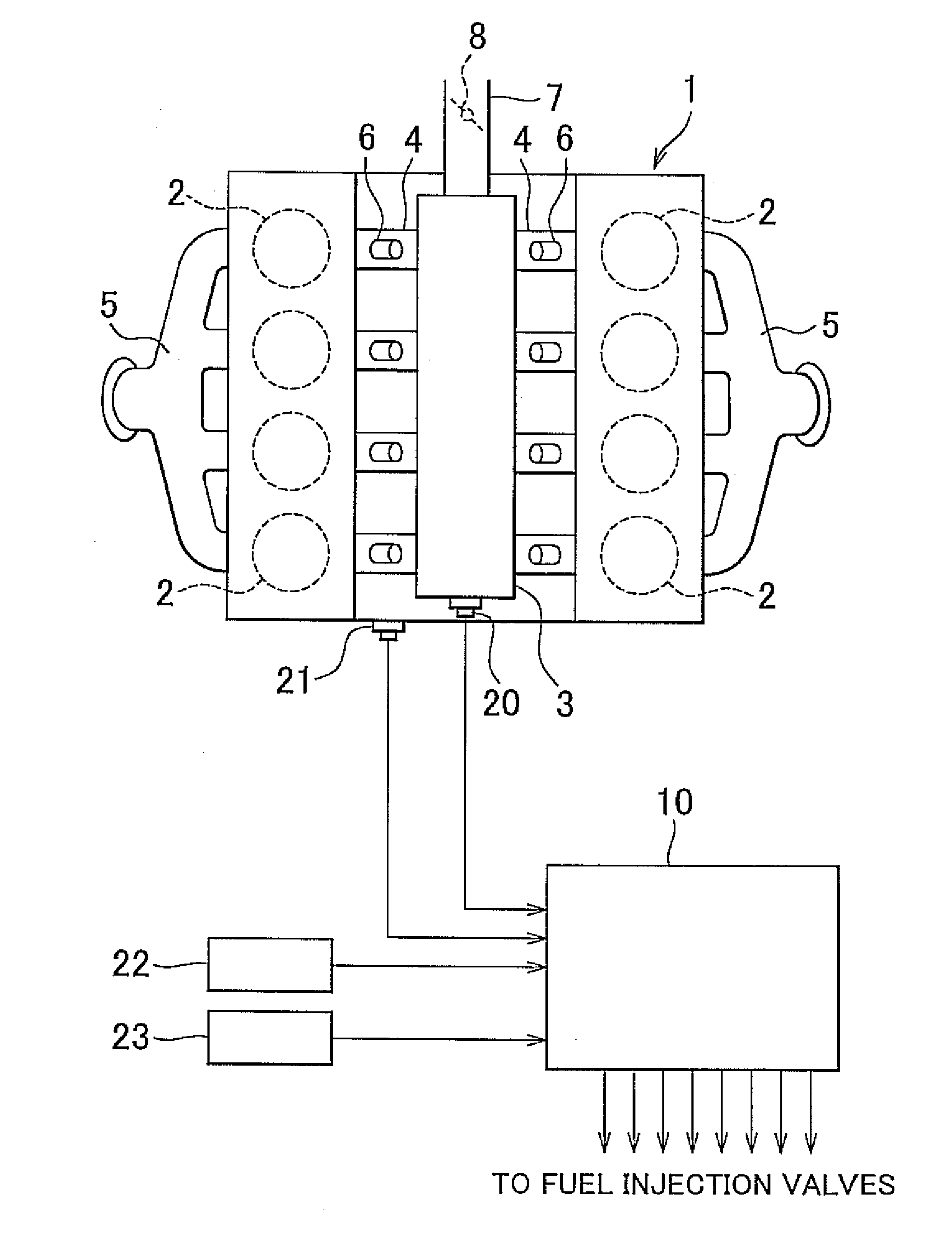
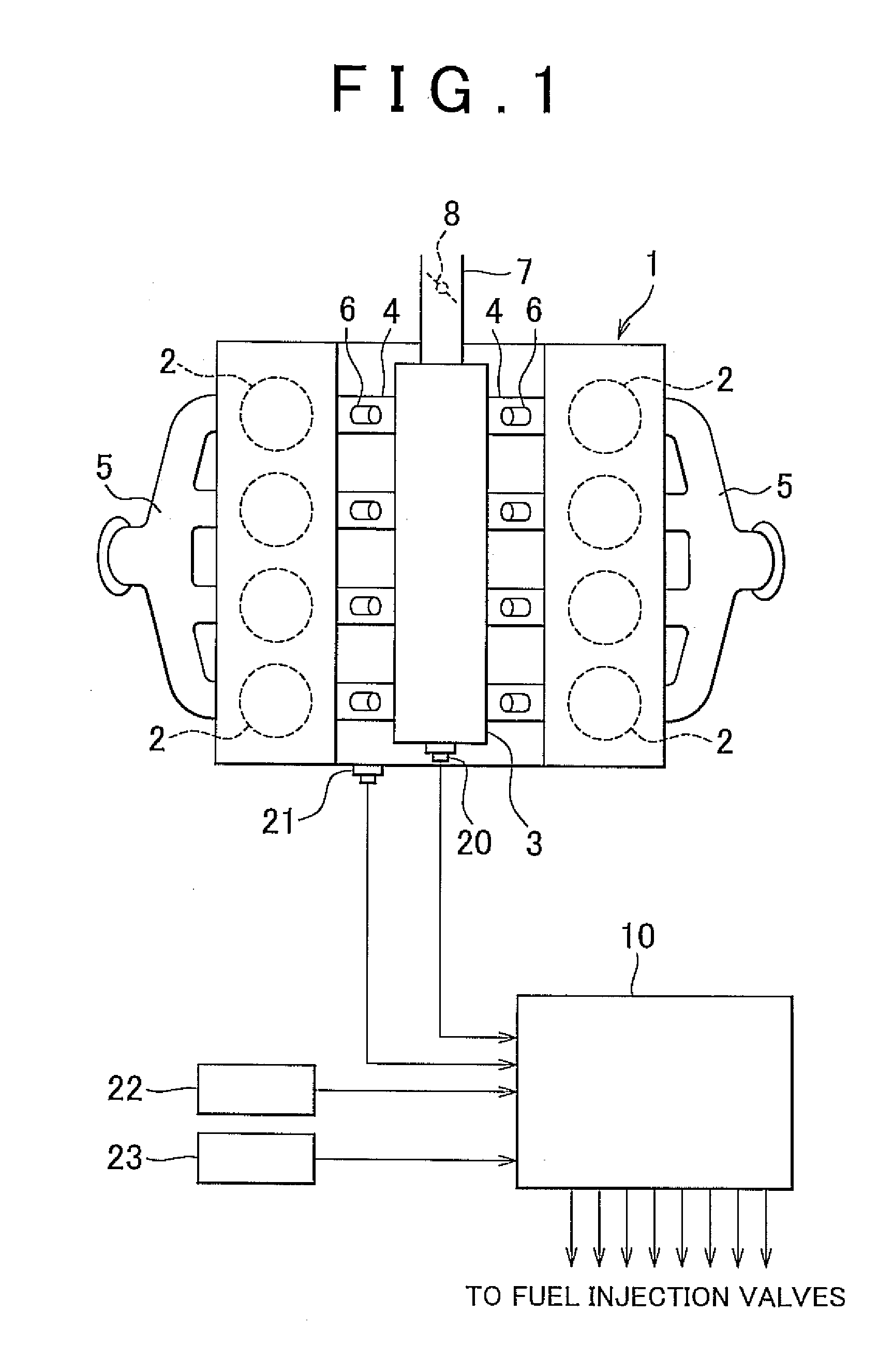
[0083]The controller of the fourth embodiment is used in the engine 1 configured as shown in FIG. 1 as in the case of the first embodiment. Thus, the following description will be made on the assumption that the engine shown in FIG. 1 is used, as in the case of the first embodiment. It should be noted that, in the fourth embodiment, the engine 1 is provided with a variable valve timing (VVT) system and an exhaust gas recirculation (EGR) system. The controller of the fourth embodiment is implemented as part of functions of the electronic control unit 10 as in the cases of the other embodiments.

[0084]The VVT system and the EGR system are used to control torque in the engine 1. However, when the retardative start control described in the above description of the first embodiment is performed, until the fuel injection into the retarded start cylinder(s) is started, the engine 1 is operated with t...

fifth embodiment

[0093]Next, a fifth embodiment of the invention will be described with reference to FIG. 8.

[0094]The controller of the fifth embodiment is used in the engine 1 configured as shown in FIG. 1 as in the case of the first embodiment. Thus, the following description will be made on the assumption that the engine shown in FIG. 1 is used, as in the case of the first embodiment. The controller of the fifth embodiment is implemented as part of functions of the electronic control unit 10 as in the cases of the other embodiments.

[0095]Various auxiliaries and electrical loads are connected to the engine 1, which are, for example, an air conditioning system, such as an air conditioner, heater, etc., a power steering system, headlights, wipers, power windows, brake lamps, etc. When these auxiliaries and the electrical loads operate, the torque produced by the engine 1 is more than a little used. When the retardative start control described in the description of the first embodiment is performed, ...

sixth embodiment

[0104]Next, a sixth embodiment of the invention will be described with reference to FIGS. 9 to 11.

[0105]The controller of the sixth embodiment is used in the engine 1 configured as shown in FIG. 1 as in the case of the first embodiment. Thus, the following description will be made on the assumption that the engine shown in FIG. 1 is used, as in the case of the first embodiment. The controller of the sixth embodiment is implemented as part of functions of the electronic control unit 10 as in the cases of the other embodiments.

[0106]FIG. 9 is a diagram showing both the behavior of the rotational speed of the engine 1 and the variation in the intake piping pressure when operation is changed from partial-cylinder operation to all-cylinder operation. The partial-cylinder operation herein means the operation, in which the engine is operated with the use of the normal start cylinder(s) only. The all-cylinder operation herein means the operation after the initial fuel injection has been com...


PUM


Abstract

An internal combustion engine is started by performing fuel supply into part of a plurality of cylinders included in the internal combustion engine. After the magnitude of the negative pressure produced in intake piping of the internal combustion engine exceeds a predetermined reference value, fuel supply into the remaining cylinder(s) is started.

Description

CROSS-REFERENCE TO RELATED APPLICATIONS[0001]This application claims priority to Japanese Patent Application No. 2010-028901 filed on Feb. 12, 2010, which is incorporated herein by reference in its entirety including the specification, drawings and abstract.BACKGROUND OF THE INVENTION[0002]1. Field of the Invention[0003]The invention relates to an internal combustion engine controller and in particular to a controller for a multi-cylinder internal combustion engine.[0004]2. Description of the Related Art[0005]In an internal combustion engine, fuel injected from a fuel injection valve into an intake port is partially vaporized and the remaining fuel attaches to the wall surface of the intake port. The fuel that attaches to the intake port wall surface is vaporized by the negative pressure in intake piping and the heat supplied from the intake port wall surface and forms a mixture together with the vaporized part of the fuel subsequently injected from the fuel injection valve. During ...

Claims


Application Information

Patent Timeline
Patent Type & Authority Applications(United States)
IPC IPC(8): F02D41/06
CPCF02D41/0087F02D41/047F02D2250/41F02D2200/0406F02D41/064
Inventor ASO, KOJITANAKA, HIROSHI
Owner TOYOTA JIDOSHA KK
Why Eureka
Try Eureka