Arrangement and method for supplying breathing gas for respiration

a breathing gas and arrangement method technology, applied in the direction of respirator, valve, operating means/releasing devices, etc., can solve the problems of reducing the anesthesia cost of hospitals, reducing the environmental effect, and reducing the cost of exhaust gas

Inactive Publication Date: 2011-08-18
GENERAL ELECTRIC CO
View PDF2 Cites 23 Cited by
  • Summary
  • Abstract
  • Description
  • Claims
  • Application Information

AI Technical Summary

Benefits of technology

[0014]In an embodiment, an arrangement for supplying a breathing gas for a respiration includes a reciprocating unit receiving an inspiration gas flow adapted to control respiratory movements and a gas mixer for supplying a fresh gas flow. The arrangement for supplying a breathing gas for a respiration also includes a breathing circuit for conducting an expiration gas flow to the reciprocating unit and for conducting the fresh gas flow from the gas mixer for the respiration and for conducting the gas flow from the reciprocating unit for an inspiration, the breathing circuit comprising a CO2 remover for removing carbon dioxide from the gas. The arrangement for supplying a breathing gas for a respiration further includes a first bypass passage bypassing the reciprocating unit and connecting the breathing circuit to the inspiration gas flow upstream the reciprocating unit.
[0015]In another embodiment, a method for supplying a breathing gas for a respiration includes supplying an inspiration gas flow to a reciprocating unit to control respiratory movements and supplying a fresh gas flow to a breathing circuit. The method for supplying a breathing gas for a respiration also includes conducting along a breathing circuit an expiration gas flow to the reciprocating unit and the fresh gas flow for the respiration and a gas flow from the reciprocating unit for inspiration, and removing c

Problems solved by technology

An expired gas comprises a lot of expensive and environment-hostile anesthesia gases.
The re-breathing circuit saves anesthesia gases, and hence lowers the hospitals anesthesia expenses, and decreases environment effects.
The open breathing cir

Method used


Image

  • Arrangement and method for supplying breathing gas for respiration
  • Arrangement and method for supplying breathing gas for respiration
  • Arrangement and method for supplying breathing gas for respiration

Examples


Embodiment Construction

[0024]Specific embodiments are explained in the following detailed description making a reference to accompanying drawings. These detailed embodiments can naturally be modified and should not limit the scope of the invention as set fort in the claims.

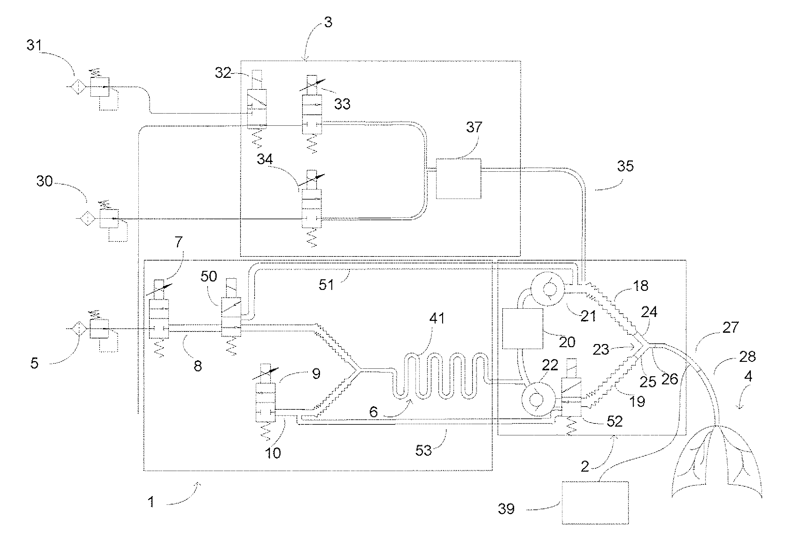
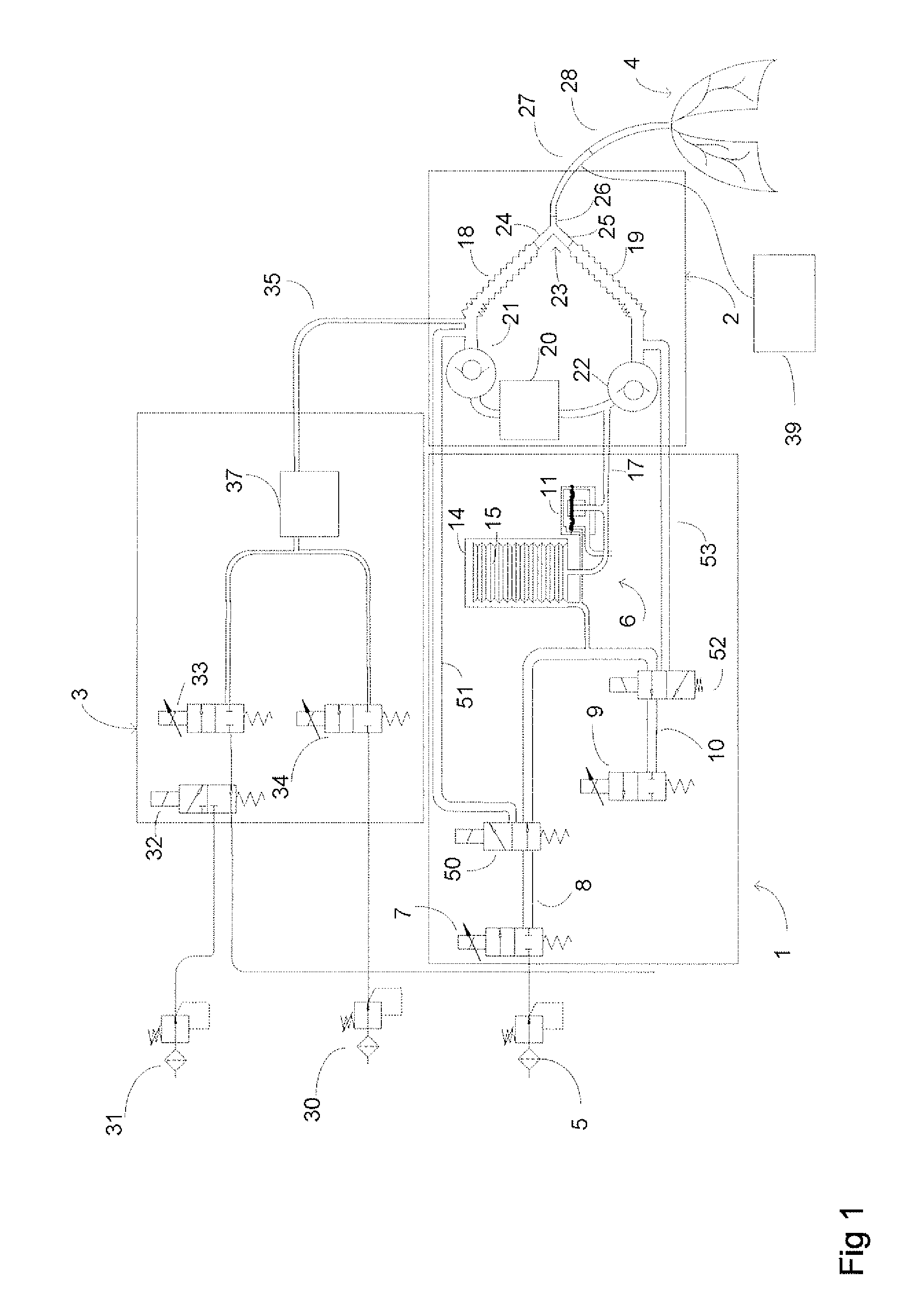
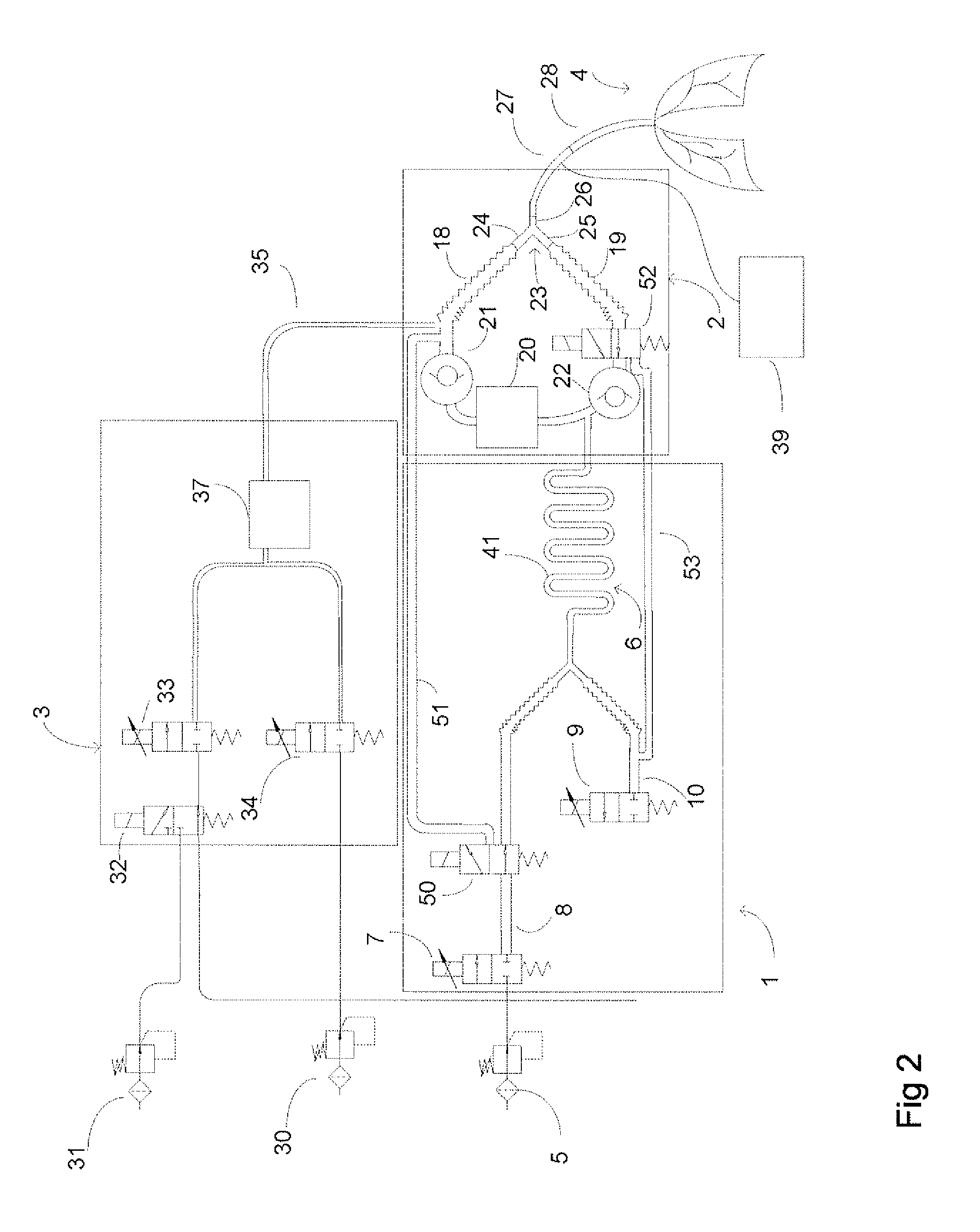
[0025]FIGS. 1 and 2 shows an arrangement for exchanging between a re-breathing circuit and open circuit modes in an anesthesia system. The anesthesia system comprises a ventilator 1, a breathing circuit 2 and a fresh gas mixer 3. A subject 4 is connected to the breathing circuit 2 by means of an endotracheal tube 28.

[0026]In FIG. 1 the ventilator 1 is connected to a gas supply 5, which is typically pressurized air or sometimes also oxygen. The ventilator 1 comprises a reciprocating unit 6 for compressing gas towards lungs of the subject to facilitate the inspiration, a flow control valve 7 to control the inspired gas flow from the gas supply 5 along a first canal 8 towards the reciprocating unit 6. Further the ventilator 1 comprises an ...


PUM


Abstract

An apparatus and method for supplying a breathing gas for a respiration. The apparatus includes a reciprocating unit configured to receive an inspiration gas flow and adapted to control respiratory movements. The apparatus also includes a gas mixer for supplying a fresh gas flow. The apparatus also includes a breathing circuit configured to conduct an expiration gas flow to the reciprocating unit and to conduct the fresh gas flow from the gas mixer for the respiration and to conduct the gas flow from the reciprocating unit for an inspiration, the breathing circuit comprising a CO2 remover configured to remove carbon dioxide from the gas. The apparatus also includes a first bypass passage configured to permit bypassing the reciprocating unit and connecting the breathing circuit to the inspiration gas flow upstream from the reciprocating unit.

Description

CROSS-REFERENCE TO RELATED APPLICATIONS[0001]Not ApplicableSTATEMENT REGARDING FEDERALLY SPONSORED RESEARCH OR DEVELOPMENT[0002]Not ApplicableNAMES OF PARTIES TO A JOINT RESEARCH AGREEMENT[0003]Not ApplicableREFERENCE TO A SEQUENCE LISTING, A TABLE, OR COMPUTER PROGRAM LISTING APPENDIX SUBMITTED ON COMPACT DISC[0004]Not ApplicableBACKGROUND OF THE INVENTION[0005]1. Field of the Invention[0006]This disclosure relates generally an arrangement and method for supplying a breathing gas for a respiration.[0007]2. Description of Related Art[0008]Hospital efficiency requirements get more demanding, more patients have to be taken through a surgery process in a shorter time and less costs. In spite of all, a patient safety is a primary requirement. Anesthesia machines are used for anesthetizing and ventilating patients in hospital operating rooms, intensive care units or other patient care places.[0009]A patient breathing circuit can be a re-breathing circuit or an open circuit. The re-breath...

Claims


Application Information

Patent Timeline
IPC IPC(8): A61M16/22A61M16/08A61M16/20
CPCA61M16/12A61M16/20A61M16/208A61M16/202A61M2205/103A61M2205/106A61M16/0833A61M16/22A61M16/204A61M16/205
Inventor LAHDE, NINNAHEINONEN, ERKKI
Owner GENERAL ELECTRIC CO
Why Eureka
Try Eureka