Adjustable display mount

a display mount and adjustable technology, applied in the direction of suspension devices, furniture parts, machine supports, etc., can solve the problems of entertainment centers occupying significant floor space, the display options of such devices are quite limited, etc., to achieve optimal viewing position/orientation, easy modulation, and overcome system misalignment

Active Publication Date: 2011-08-18
PEERLESS INDS
View PDF61 Cites 41 Cited by
  • Summary
  • Abstract
  • Description
  • Claims
  • Application Information

AI Technical Summary

Benefits of technology

[0006]Various embodiments comprise systems for mounting a display device, such as an LCD and plasma flat panel display. The mounting systems are selectively adjustable to provide adjustment of the position and orientation of an attached display in several degrees of freedom. The mounting systems are configured to enable a user to make the various adjustments without the use of tools. Instead, the position and orientation of the attached display may be readily modulated by hand operation of a plurality of positioners that alone and / or in combination enable independent translation and rotation of the display relative to the mounting surface. Adjustability of the mounting system may be used to obtain an optimal viewing position / orientation of the attached display, as well as to overcome misalignment of the system when it is attached to the mounting surface and / or variation in the mounting surface.

Problems solved by technology

Because conventional “tube” televisions have a relatively large depth, the display options for such devices are quite limited.
Such stands or entertainment centers can take up significant floor space, which is often undesirable.

Method used


Image

  • Adjustable display mount
  • Adjustable display mount
  • Adjustable display mount

Examples


Embodiment Construction

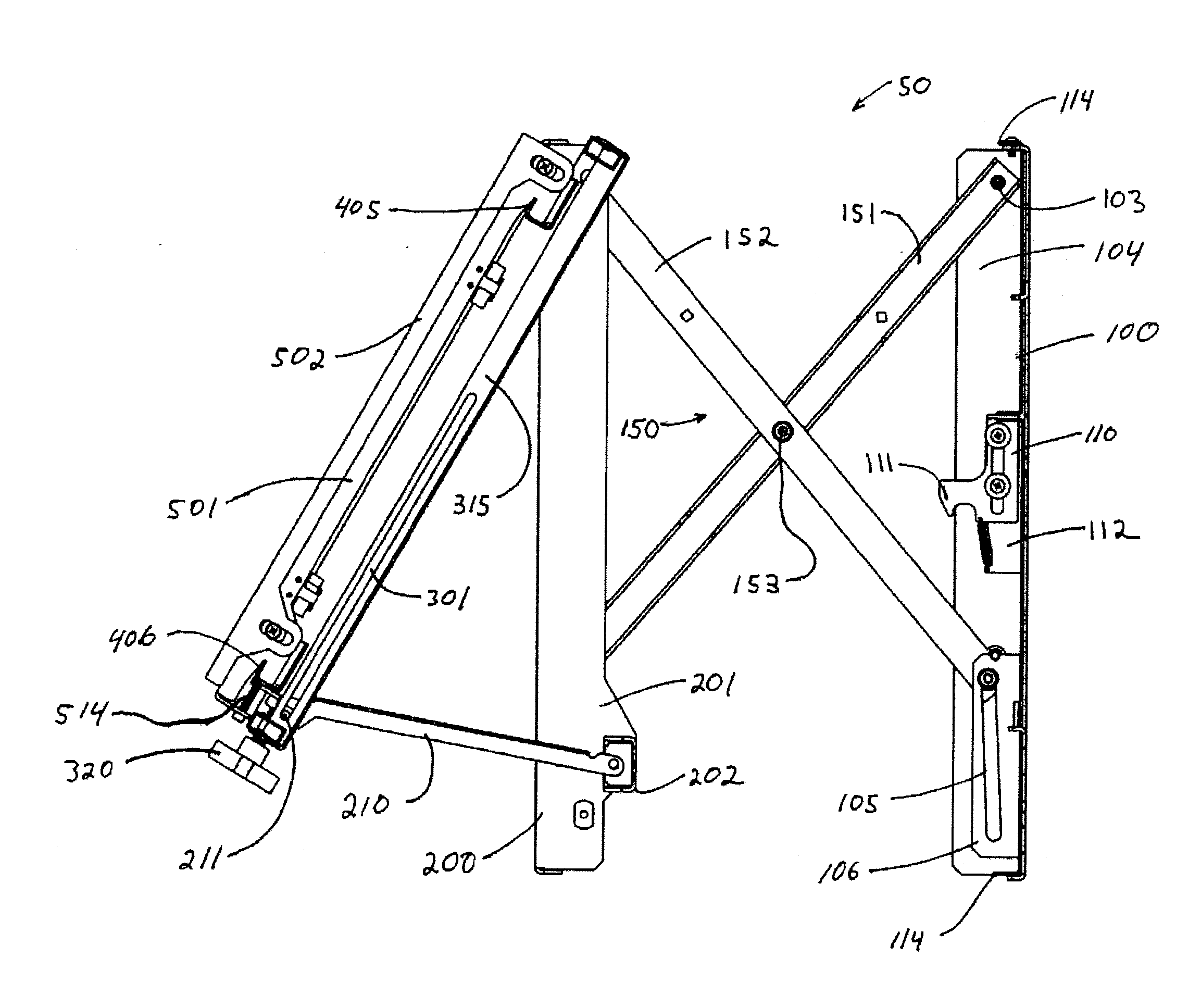
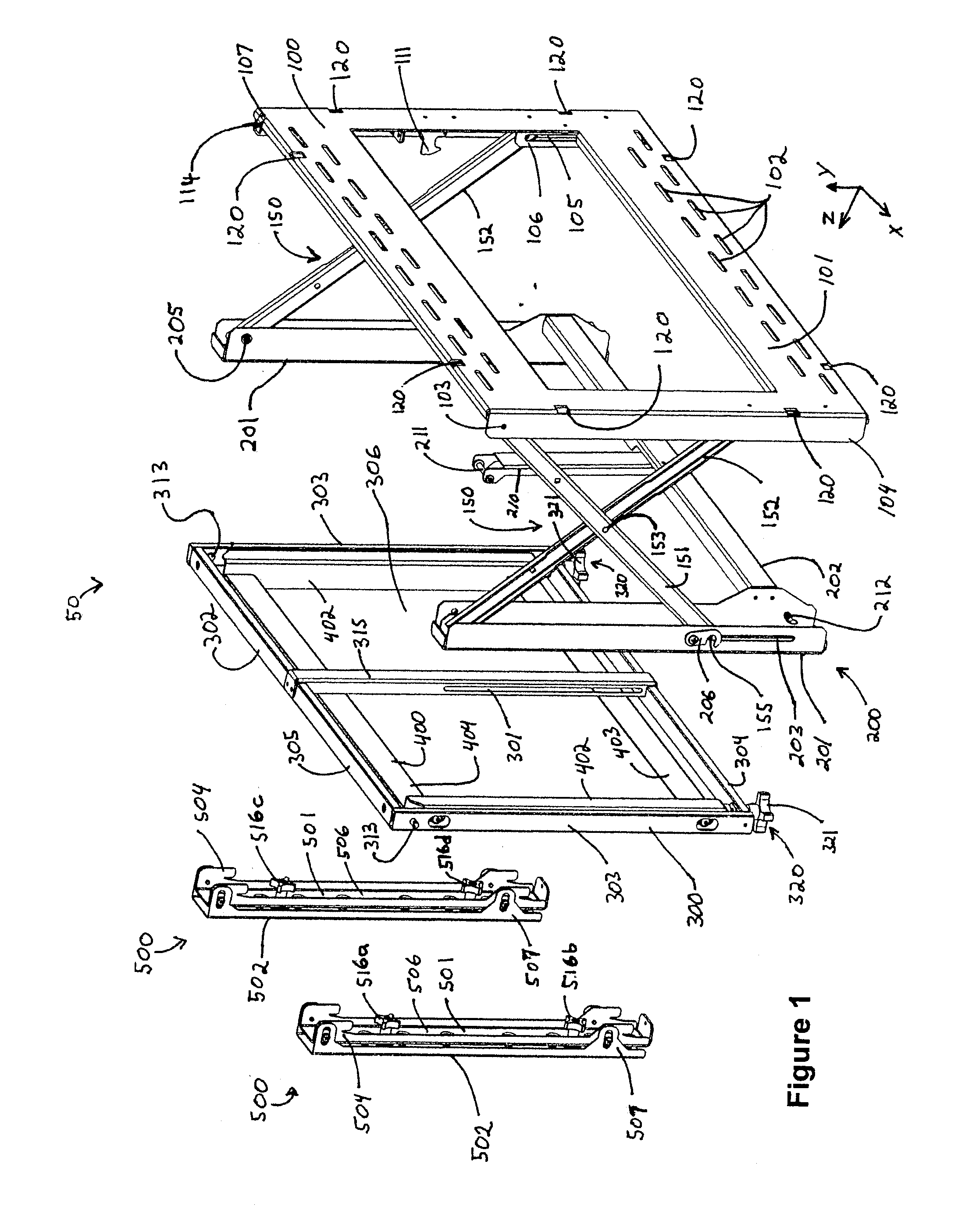
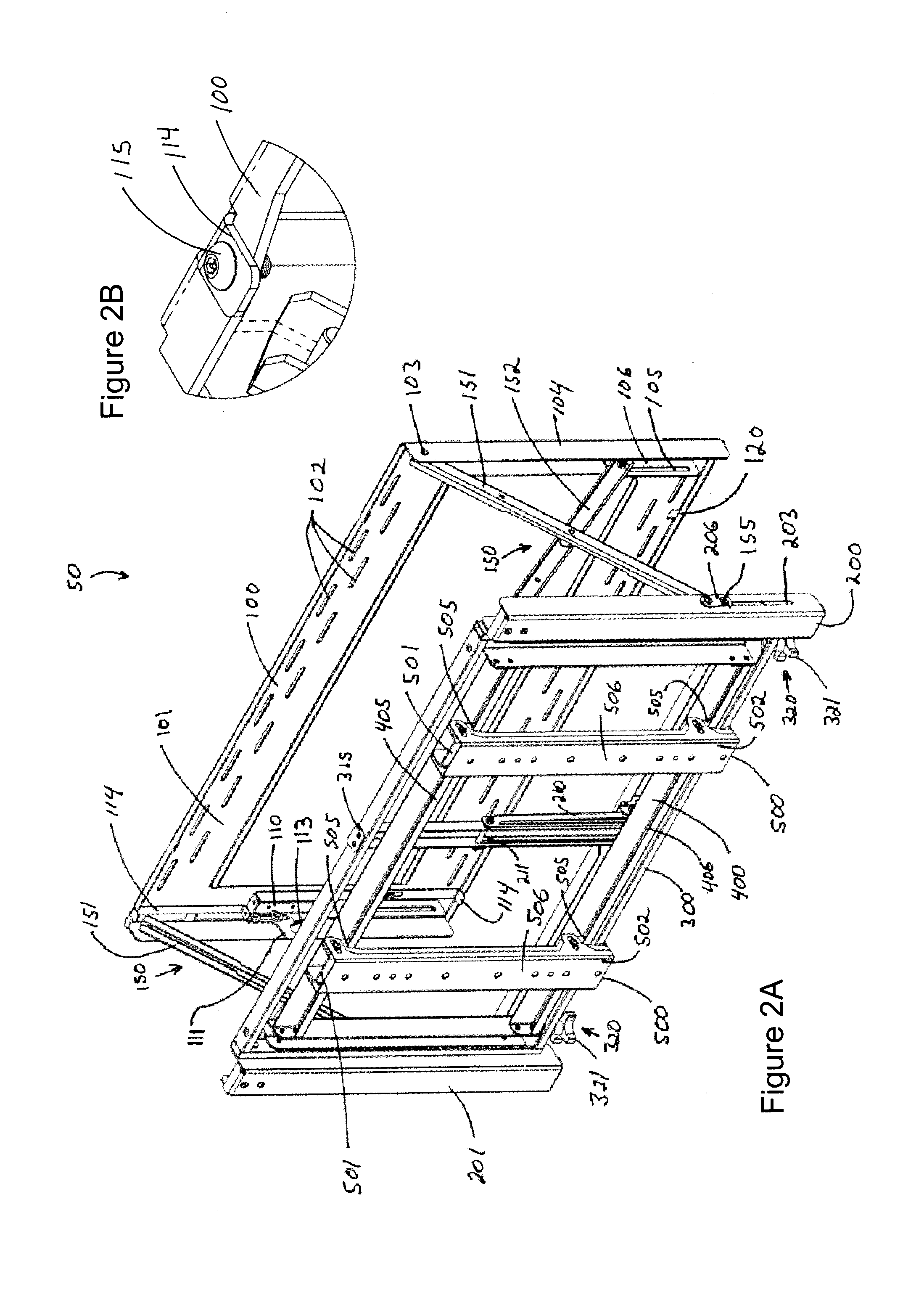
[0027]FIGS. 1-12 illustrate a mounting system 50 constructed in accordance with an embodiment of the present invention. The mounting system 50 is configured to attach a display device to a mounting surface such as a wall or other surface. Various portions of the mounting system 50 are selectively movable in relation to each other such that the position and orientation of the attached display may be adjusted in a plurality of dimensions or degrees of freedom. The various features of the mounting system 50 provide for independent control of translational and rotational degrees of freedom of the attached display relative to the mounting surface. Through adjustment of the various features of the mounting system 50, optimization of the position and orientation of the attached display can be achieved relative to a mounting surface and / or adjacent displays when the mounting system 50 is used in the context of a video wall application comprising an array of display devices.

[0028]With refere...


PUM


Abstract

A mounting system for mounting a display device to a surface, the mounting system adjustable in multiple degrees of freedom to selectively position and orientate the attached device relative to the mounting surface and/or other collocated display devices. According to various embodiments, a surface bracket is configured to attach to a mounting surface and an arm assembly operatively couples the surface bracket with a mount carriage. A mount bracket is movably coupled to the mount carriage and is selectively movable in a plane substantially parallel to the surface. A plurality of device bracket assemblies are coupled to the mount bracket. Each of the device bracket assemblies is selectively movable to translate, pivot and tilt the attached device.

Description

FIELD OF THE INVENTION[0001]The present invention relates generally to mounting systems for devices. More particularly, the present invention relates to adjustable mounting systems for mounting a flat-panel display and similar devices.BACKGROUND OF THE INVENTION[0002]This section is intended to provide a background or context to the invention that is recited in the claims. The description herein may include concepts that could be pursued, but are not necessarily ones that have been previously conceived or pursued. Therefore, unless otherwise indicated herein, what is described in this section is not prior art to the description and claims in this application and is not admitted to be prior art by inclusion in this section.[0003]In recent years, flat panel televisions have become enormously popular in both commercial and residential sectors. As the prices for plasma and liquid crystal display (LCD) flat panel displays have continued to fall, and the quality for the same devices have ...

Claims


Application Information

Patent Timeline
Patent Type & Authority Applications(United States)
IPC IPC(8): F16M13/02
CPCF16M11/10F16M11/2092F16M13/022F16M13/02F16M2200/061F16M11/38A47B97/001A47B2097/005F16M2200/068
Inventor STIFAL, MATTHEW WILLIAMWALTERS, JAMES D.
Owner PEERLESS INDS
Why Eureka
Try Eureka