
Mobile base for reducing lateral pressure of the body lift cylinder of a dump body

a technology of lifting cylinder and dump body, which is applied in the direction of loading transportation vehicles, transportation items, vehicles with tipping movement, etc., can solve the problems of no slack and operation of the same, and achieve the effects of reducing torsion, avoiding any flexion, and facilitating the movement of the dump body

Active Publication Date: 2011-08-18
LES PLACEMENTS MARCEL BIBEAU
View PDF7 Cites 7 Cited by
  • Summary
  • Abstract
  • Description
  • Claims
  • Application Information

AI Technical Summary

Benefits of technology

[0018]the round shape of the peripheral external part of the annular support and the collar formed by the two plates of the set of plates once attached to each other allowing the first end of the cylinder to fold and thus allowing the cylinder to extend in a constant straight line even when it is subjected to a lateral torsion.
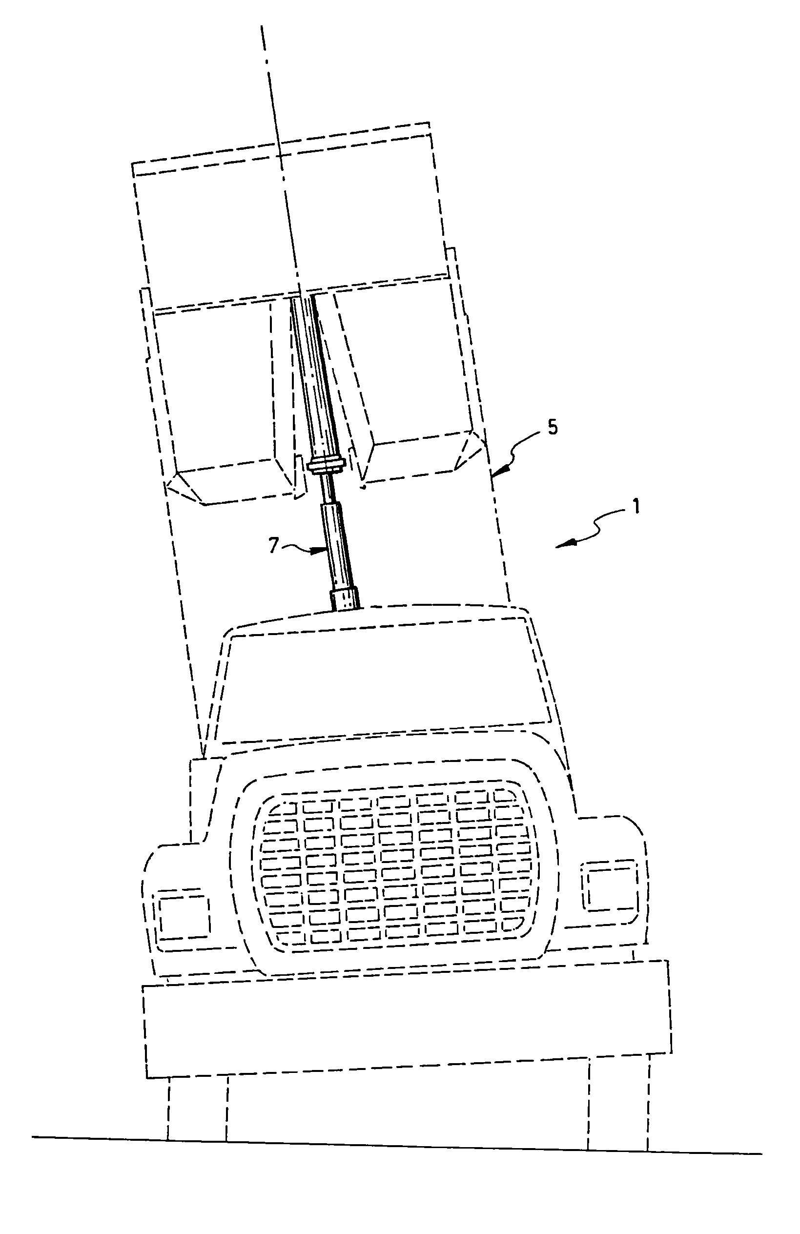
[0019]As can therefore be appreciated, the present invention permits to substantially reduce the torsion applied to the body lift cylinder, in addition to facilitate the movement of the dump body. Indeed, thanks to the mobile base, the body lift cylinder is capable of moving up while being sufficiently mobile to avoid any flexion applied to the extendable parts of the same when said body lift cylinder is extending up.

Problems solved by technology

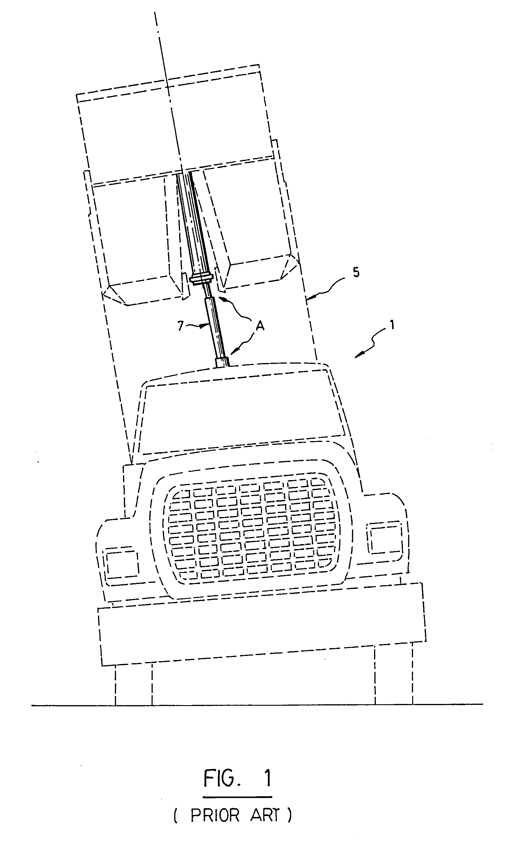
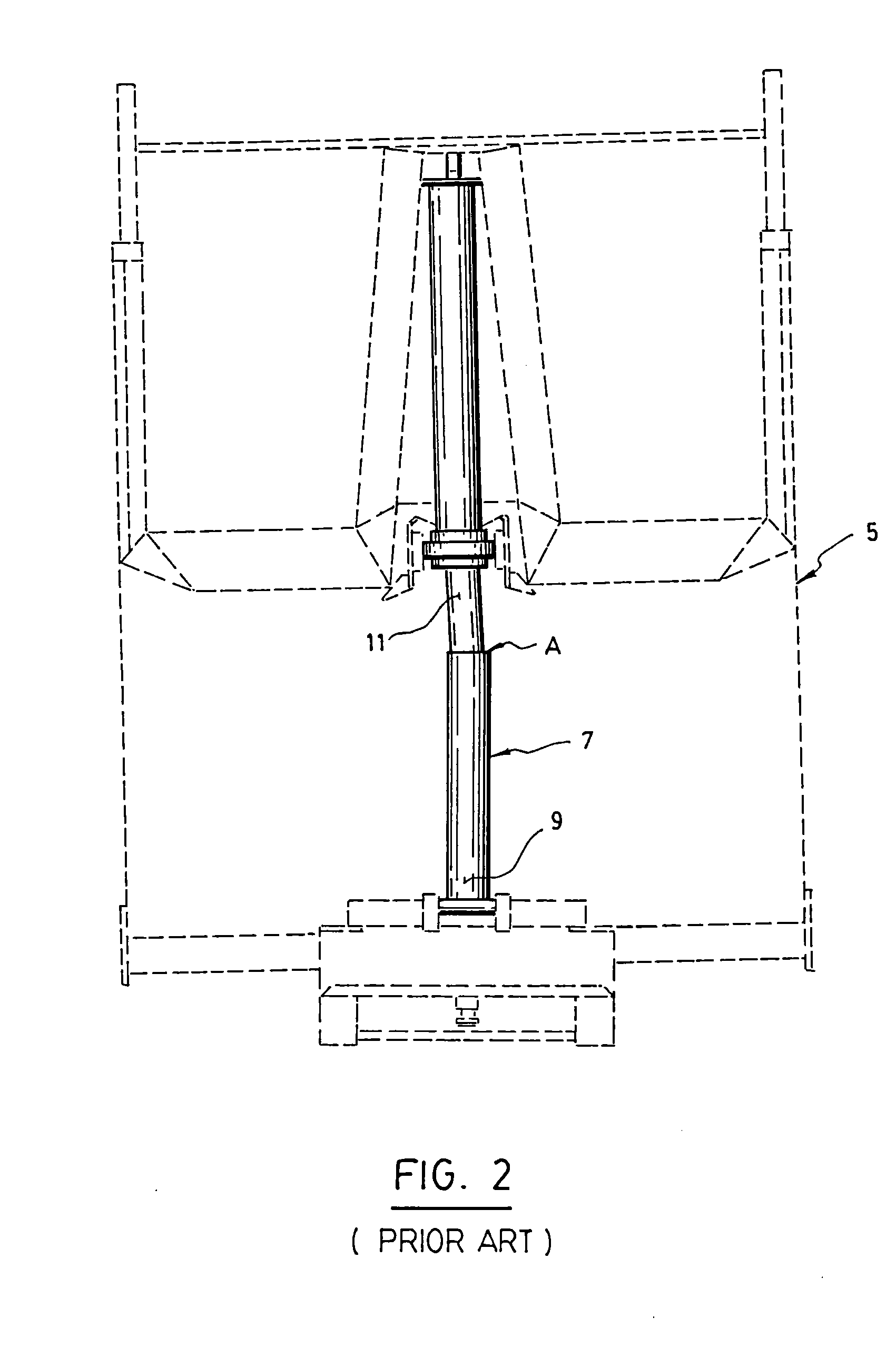
The problem that has always existed with this kind of equipment, is that there is no slack given to the body lift cylinder when the same is used for lifting up the dump body.
Then, a strong pressure can be exerted onto the inside or the outside of the body lift cylinder, which can lead to a problem of operation of the same, after some time.

Method used


Image

  • Mobile base for reducing lateral pressure of the body lift cylinder of a dump body
  • Mobile base for reducing lateral pressure of the body lift cylinder of a dump body
  • Mobile base for reducing lateral pressure of the body lift cylinder of a dump body

Examples


first embodiment

[0036]FIGS. 4 to 7c illustrate a first preferred embodiment of the invention, wherein the mobile base is numbered 13. In this first embodiment, the mobile base 13 comprises a support 15 which itself comprises a central part 17 devised to receive and hold the first end 9 of the cylinder. The support 15 also comprises two lateral parts 19 and 21 which are opposite to each other and each in the form of a tubular shaft, said shafts being aligned on a same common axis X perpendicular to the cylinder (see FIG. 5a).

[0037]In the particular embodiment shown in FIG. 4 and subsequent, one of the two cylinders, namely the one numbered 39, is provided with a central cavity intended to let pass a supply system 23 to activate the body lift cylinder 7. It can however be understood that this system 23 could be positioned in a different manner, depending on the needs and / or structure of the equipment.

[0038]The mobile base 13 also comprises a set of two holding sleeves 25 and 27, each made of two part...

second embodiment

[0046]FIGS. 13 and 14a to 14c illustrate a second preferred embodiment of the invention. In this second embodiment, the mobile base which is numbered 13′, comprises an annular support 15′ provided with a central part 17′ that is devised to receive the first end 9 of the cylinder 7. This annular support 15′ is also provided with a peripheral external part 19′ that is convex and of a round shape. The annular support 15′ is attached in a rigid manner to the first end 9′ of the cylinder 7′ by means of attachment means such as bolts 21′ insertable into holes 25′ made in a bottom wall 23′ extending under the central part 17′, in such a manner as to be screwable into holes 27′ provided for this purpose under the bottom surface of the first end 9′ of the cylinder 7.

[0047]It is worth noting that the bottom wall 23′ may be provided with a central opening to allow the supply system of the body lift cylinder 7 to pass through if it has to fit at the bottom of this cylinder 7.

[0048]Of course, an...


PUM


Abstract

Disclosed is an equipment of the type comprising a frame on which is mounted a dump body liftable by means of a body lift cylinder having two opposite ends, a first one of these ends being connected to the frame and the other one to the dump body in order to lift it up when the cylinder is extended. This equipment is characterized in that the first end of the cylinder connected to the frame is mounted on a mobile base which is fixed onto the frame in such a manner as to have some liberty of transversal inclination and thus to allow the cylinder to extend in a constant straight line even if a lateral torsion is applied onto the cylinder by the dump body when said dump body is lifted up.

Description

FIELD OF THE INVENTION[0001]The present invention relates to a mobile base especially devised for reducing lateral pressure on a body lift cylinder.[0002]More specifically, the invention relates to an equipment of the type comprising a frame on which is pivotably mounted a dump body liftable by means of a body lift cylinder, said cylinder being mounted onto the frame by means of a mobile base which is itself fixed to the frame in such a manner as to have some liberty of transversal inclination and thus to allow the cylinder to extend in a constant straight line even if a lateral torsion is applied onto the cylinder by the dump body when the same is lifted up.[0003]Advantageously but not exclusively, said equipment is actually part of a truck or a trailer on which a dump body is pivotably mounted for the transportation and unloading of a charge.TECHNOLOGICAL BACKGROUND[0004]Equipment comprising a frame on which is pivotably mounted a dump body liftable by means of a body lift cylinde...

Claims


Application Information

Patent Timeline
Patent Type & Authority Applications(United States)
IPC IPC(8): B60P1/28
CPCB60P1/045
Inventor BIBEAU, MARCEL
Owner LES PLACEMENTS MARCEL BIBEAU
Learn More