
Automobile wheel

a technology for automobile wheels and wheels, applied in the field of automobile wheels, can solve the problems of increasing the possibility of a decrease in durability, and achieve the effects of preventing swelling, improving durability, and prolonging the life of automotive wheels

Inactive Publication Date: 2011-08-18
CENTRAL MOTOR WHEEL CO LTD
View PDF7 Cites 4 Cited by
  • Summary
  • Abstract
  • Description
  • Claims
  • Application Information

AI Technical Summary

Benefits of technology

[0007]The present invention proposes an automotive wheel that includes a wheel disc provided with a front flange portion folded backward and having improved durability.

Problems solved by technology

In this case, stress concentration occurs at the joint between the axle and the automotive wheel and so on, increasing the possibility of a decrease in durability.

Method used


Image

  • Automobile wheel
  • Automobile wheel
  • Automobile wheel

Examples


Embodiment Construction

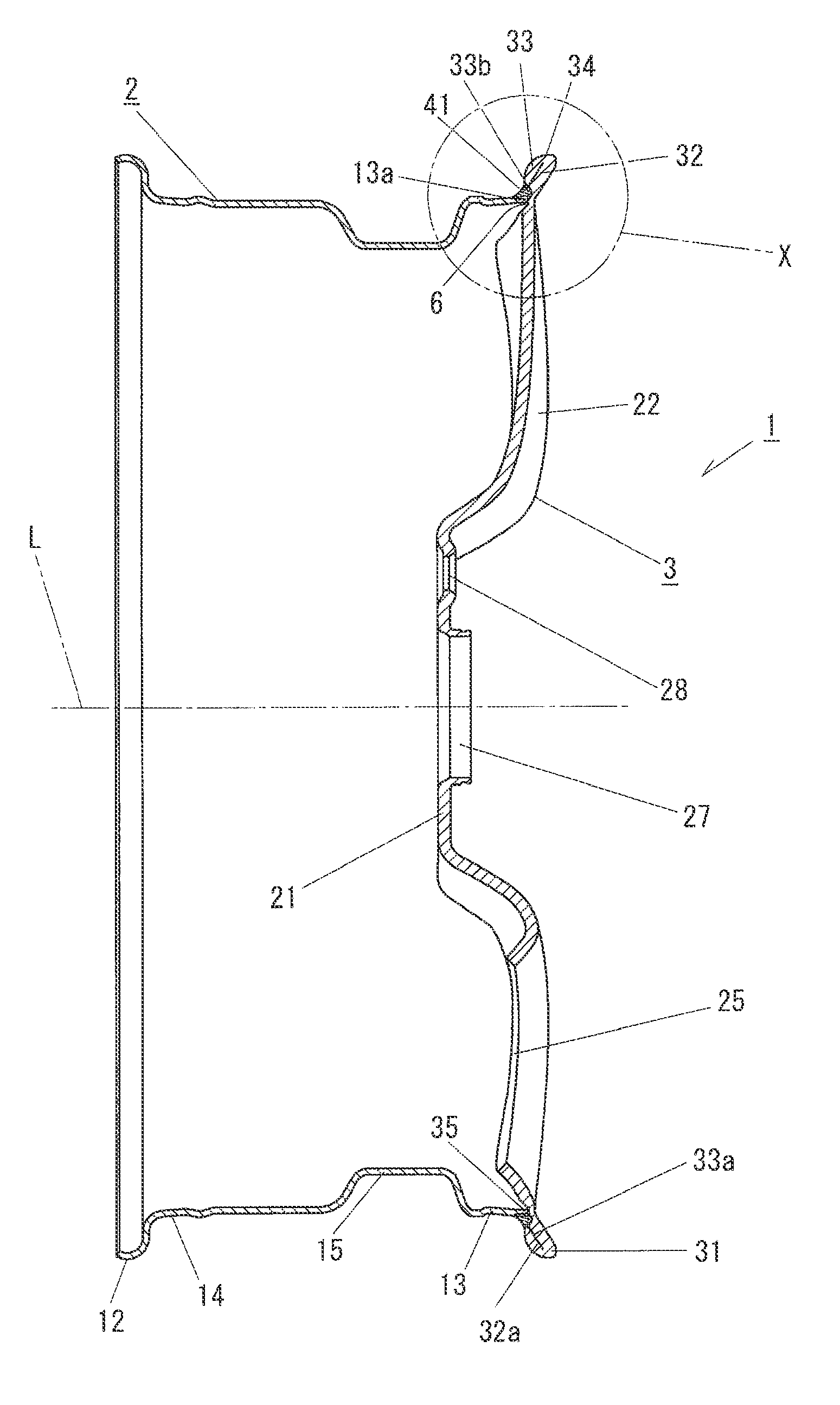
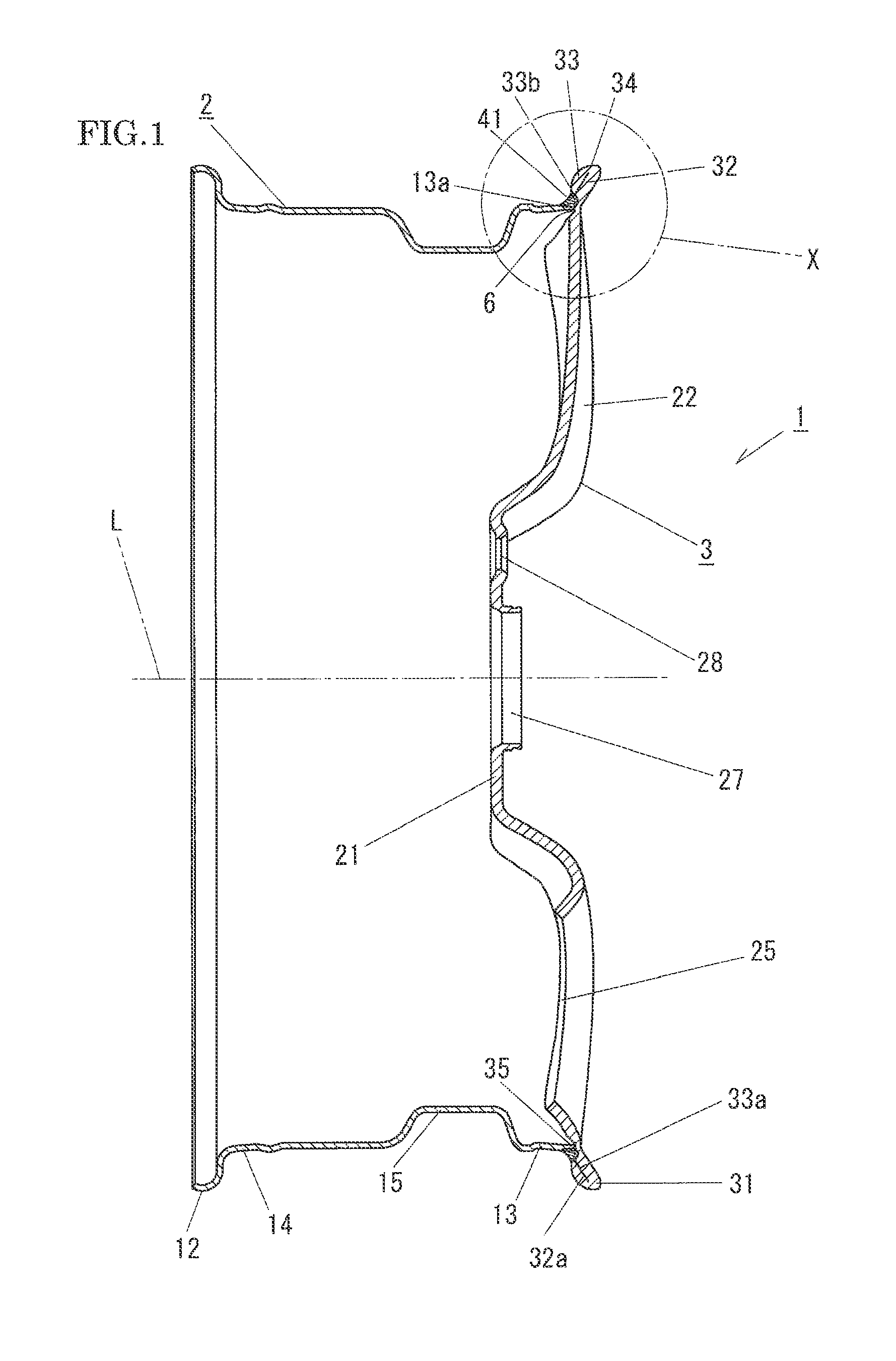
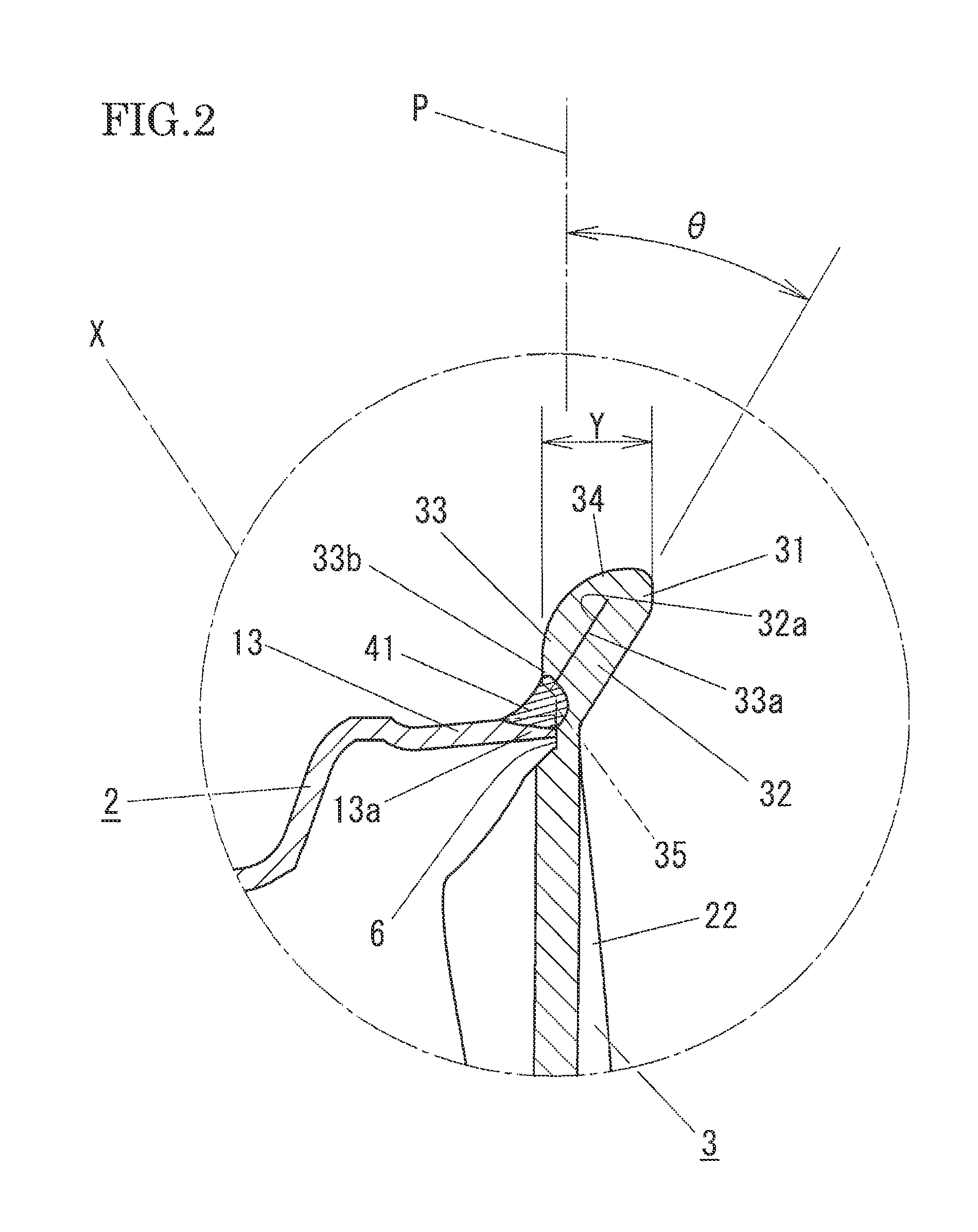
[0037]An automotive wheel 1 according to an example of the present invention will be described in detail with reference to the accompanying drawings.

[0038]FIG. 1 is a vertical cross-sectional view of the automotive wheel 1. The automotive wheel 1 is a so-called two-piece steel wheel formed by joining a wheel rim 2 and a wheel disc 3, each formed from a flat steel plate, to each other. The automotive wheel 1 has a full-face configuration in which a front flange portion 31 is provided at an outer peripheral edge portion of the wheel disc 3. In the example, the direction from the back surface side of the wheel disc 3 toward the design surface side (the direction from left to right in FIG. 1) is defined as a “forward direction”, and the opposite direction is defined as a “backward direction”. Also, the direction toward the center axis L of the automotive wheel 1 along the radial direction of the wheel is defined to as a “radially inward direction”, and the opposite direction is defined ...


PUM


Abstract

A front flange portion formed at an outer peripheral edge portion of a wheel disc includes an annular front peripheral portion provided on a design surface side and an annular back peripheral portion folded backward from the annular front peripheral portion to extend radially inwardly and in surface contact with a back surface of the annular from peripheral portion, and the annular front peripheral portion and the annular back peripheral portion are integrally inclined to the surface side. Therefore, the front flange portion can mitigate stress concentration on the front flange portion due to a load generated while the automobile is running. In addition, the front flange portion has, because of its shape, high durability against a radially inward load generated by a contact with a curbstone or the like.

Description

CROSS-REFERENCE TO PRIOR APPLICATIONS[0001]Priority is claimed to Japanese Patent Application No. 2010-033096, filed on Feb. 18, 2010, which is hereby incorporated by reference in its entirety herein.FIELD OF THE INVENTION[0002]The present invention relates to an automotive wheel in which a wheel rim on which a tire is to be mounted and a wheel disc to which an axle is to be coupled are welded to each other for integration.BACKGROUND[0003]There are so-called two-piece automotive wheels in which a generally cylindrical wheel rim and a generally disc-like wheel disc are welded to each other. As such two-piece automotive wheels, there are known full-face automotive wheels in which a front flange portion is formed at an outer peripheral edge portion of the wheel disc.[0004]An example of the full-face automotive wheels is proposed in No. JP-A-Hei 11-042901 (“JP '901”), for example. As shown in FIG. 8, a wheel rim “f” includes a front bead seat portion “g” provided at one opening edge por...

Claims


Application Information

Patent Timeline
Patent Type & Authority Applications(United States)
IPC IPC(8): B60B25/00B60B21/02
CPCB60B3/04
Inventor CHASHIRO, KATSUYA
Owner CENTRAL MOTOR WHEEL CO LTD
Learn More