Focus detection apparatus and control method therefor

a technology of focus detection and control method, which is applied in the direction of focusing aids, instruments, television systems, etc., can solve the problems of varying the amount of light between the first and second images, and the possibility of distance measurement errors

Inactive Publication Date: 2011-08-18
CANON KK
View PDF7 Cites 53 Cited by
  • Summary
  • Abstract
  • Description
  • Claims
  • Application Information

AI Technical Summary

Benefits of technology

[0013]According to yet another aspect of the present invention, there is provided a control method for a focus detection unit for setting a focus detection area corresponding to a selected focus state detecting position, and detecting a defocus amount in the focus detection area on the basis of a phase difference between two images corresponding to the focus detection area, the control method comprising: a reading step of reading out a pair of image signals, from an image sensor comprising a plurality of pixels for focus detection for receiving a pair of respective light beams transmitted through different pupil areas of a photographing lens, wherein the pair of image signals are output from the plurality of pixels for focus detection; a determination step of determining a tilt of the focus detection area, depending on positional information on the focus state detecting position with respect to an angle of image sensing view and exit window information on the photographing lens; and a detection step of detecting the defocus amount on the basis of a phase difference between a pair of images obtained from pixels for focus detection corresponding to the focus detection area with a tilt determined in the determination step, from among the plurality of pixels for focus detection.
[0014]According to still yet another aspect of the present invention, there is provided a control method for a focus detection unit for setting a focus detection area corresponding to a selected focus state detecting position, and detecting a defocus amount in the focus detection area on the basis of a phase difference between two images corresponding to the focus detection area, the control method comprising: a reading step of reading out a pair of image signals, from an image sensor comprising a plurality of pixels...

Problems solved by technology

On the other hand, problems caused by vignetting include not only the imbalance in the amount of light between first and second images, but also the movement of an image at a tilt due...

Method used


Image

  • Focus detection apparatus and control method therefor
  • Focus detection apparatus and control method therefor
  • Focus detection apparatus and control method therefor

Examples


first embodiment

[0037](First Embodiment)

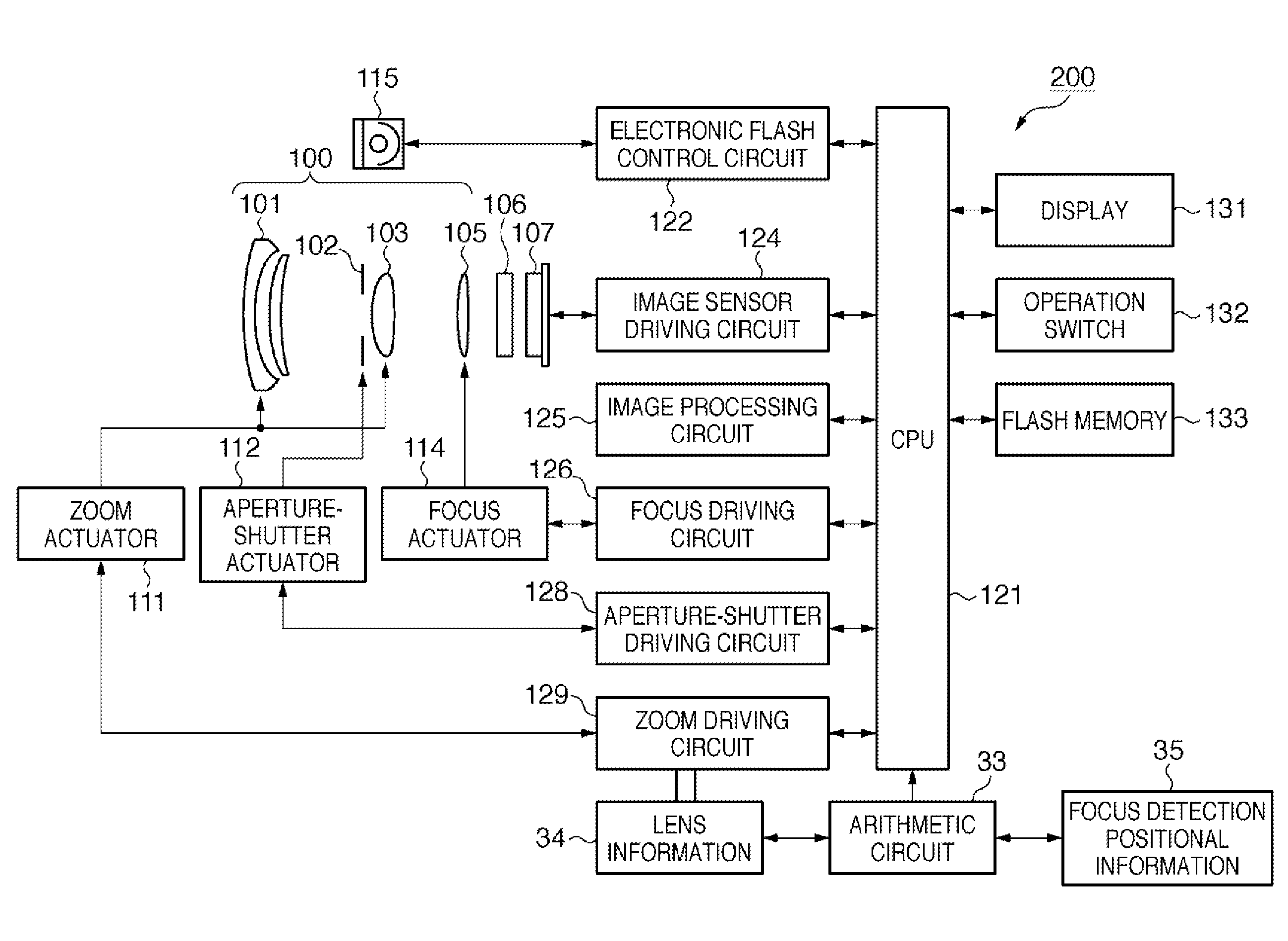
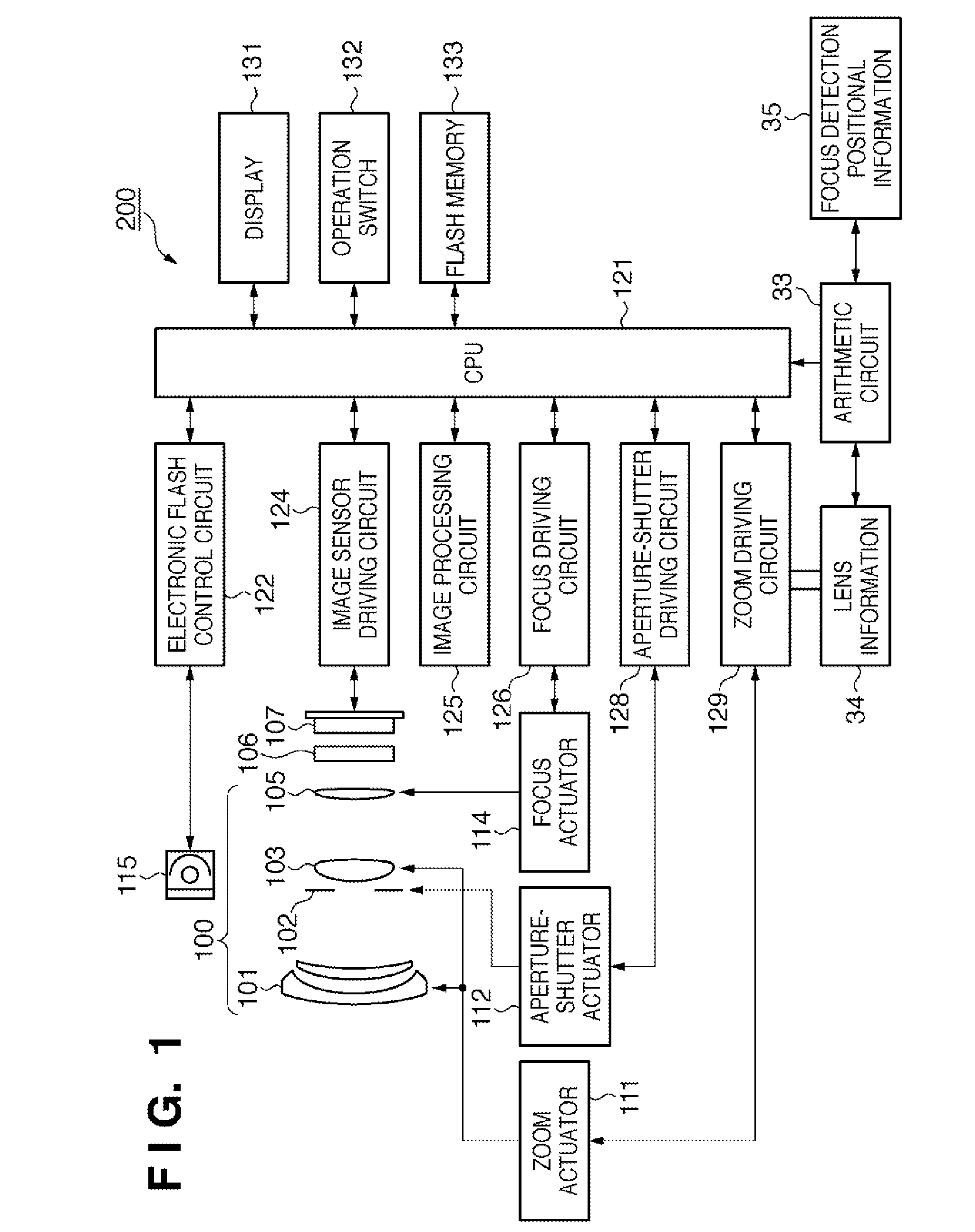
[0038]FIG. 1 is a block diagram illustrating the configuration of a camera as an example of an optical instrument in the present embodiment.

[0039]In FIG. 1, reference numeral 200 denotes a camera, which is shown as an electronic camera including a camera main body with an image sensor, combined with a photographing lens 100. Reference numeral 101 denotes a first group of lenses disposed at the end of the photographing lens 100, which is held movably in either direction of the optical axis. Reference numeral 102 denotes an aperture-shutter, which both regulates the amount of light for shooting by adjusting its opening diameter and serves as a shutter for adjusting the period of exposure in still image shooting. Reference numeral 103 denotes a second group of lenses. The aperture-shutter 102 and the second group of lenses 103 move together in either direction of the optical axis, and work in conjunction with the first group of lenses 101 moving in either direct...

second embodiment

[0101](Second Embodiment)

[0102]Next, a second embodiment of the present invention will be described. It should be noted that since the entire camera has the same configuration as described in the first embodiment, description of the configuration will be omitted here.

[0103]While the first embodiment described above allows any area to be set as the focusing area depending on an image to be shot, the present embodiment is different from the first embodiment in that the focus detection areas are fixed.

[0104]FIGS. 15A and 15B are diagrams illustrating focus detection areas in the second embodiment of the present invention.

[0105]In FIG. 15A, reference numerals 50-1 to 50-15 denote fifteen fixed focus detection frames, and in FIG. 15B, reference numerals 51-1 to 51-15 denote fifteen fixed focus detection areas.

[0106]In the present embodiment, a case of a fixed focus lens is assumed, or a case is assumed in which the shape of vignetting is not really changed even if the zoom ratio of the l...


PUM


Abstract

A focus detection apparatus includes an image sensor including pixels for focus detection for receiving a pair of respective light beams transmitted through different pupil areas of a photographing lens to output a pair of signals; an acquisition unit for acquiring exit window information on the photographing lens; an arithmetic circuit for calculating a tilt for detection area in the detecting position, depending on an image height for a detecting position in which a focus state is detected and on the exit window information; and a calculation unit for calculating the shape of the detection area depending on the calculated tilt, in which the defocus amount is detected on the basis of a phase difference between the pair of signals obtained from pixels for focus detection included in the calculated detection area.

Description

TECHNICAL FIELD[0001]The present invention relates to a focus detection apparatus for detecting a focus state of a photographing lens on the basis of images obtained from a solid-state image sensing device, and a control method for the focus detection apparatus.BACKGROUND ART[0002]Methods for detecting focus states of photographing lenses include a phase difference detection method (deviation method).[0003]In the phase difference detection method, light beams passing through an exit pupil of a photographing lens are divided in two, and the light beams divided in two are respectively received by a pair of sensors for focus detection. Then, the movement of the photographing lens required for focusing is obtained directly by detecting the deviations of output signals obtained in response to the amount of light received, that is, the deviations between the relative positions of the light beams in the dividing direction thereof. Thus, with one operation for accumulation carried out throu...

Claims


Application Information

Patent Timeline
IPC IPC(8): H04N5/228G02B7/34G03B13/36H04N5/232H04N5/335H04N5/369H04N5/374
CPCG02B7/34H04N5/23212G03B13/36G02B7/36H01L27/14623H01L27/14627H01L27/1462H04N23/672H04N25/134
Inventor TAKAMIYA, MAKOTO
Owner CANON KK
Why Eureka
Try Eureka