Developing device and process cartridge
- Summary
- Abstract
- Description
- Claims
- Application Information
AI Technical Summary
Benefits of technology
Problems solved by technology
Method used
Image
Examples
embodiment 1
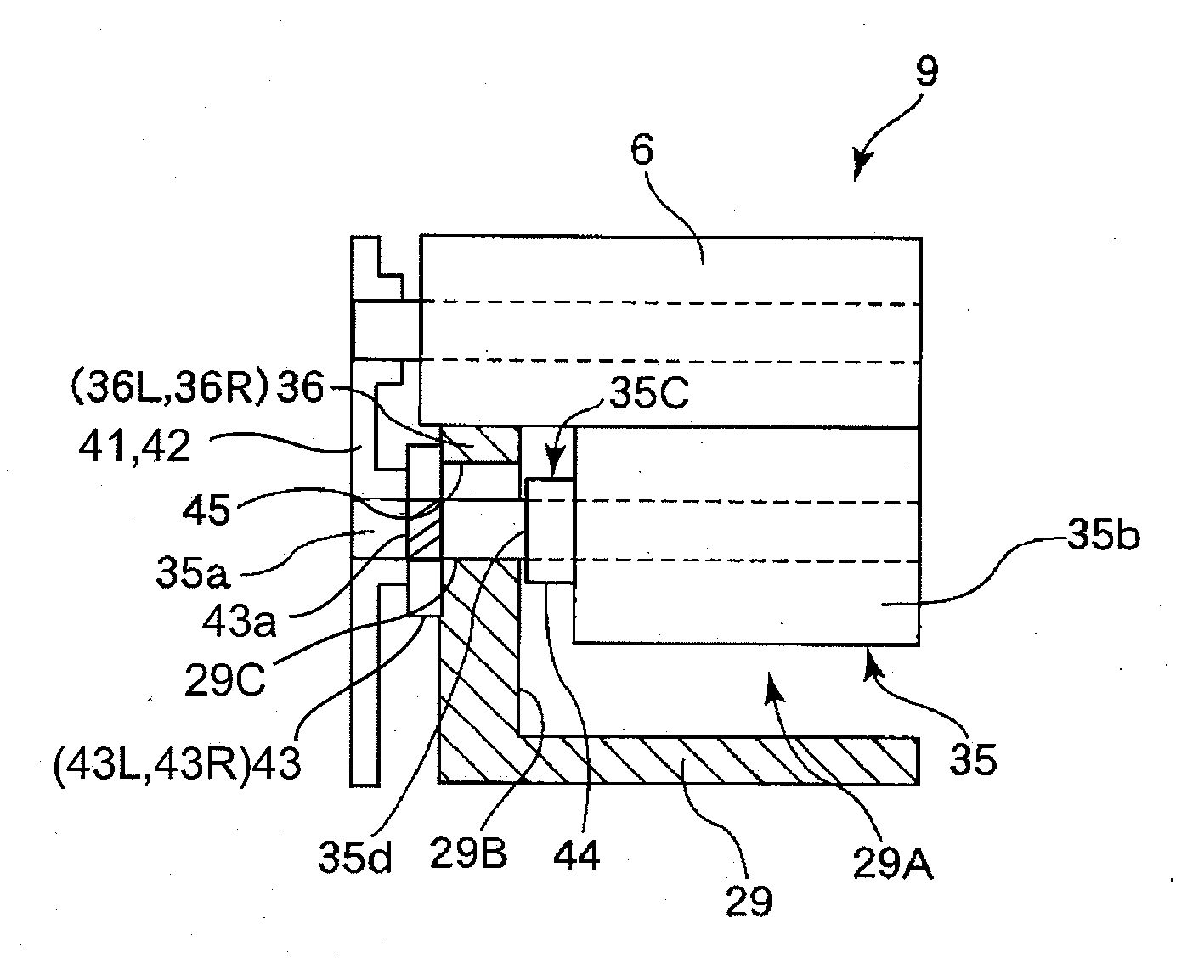
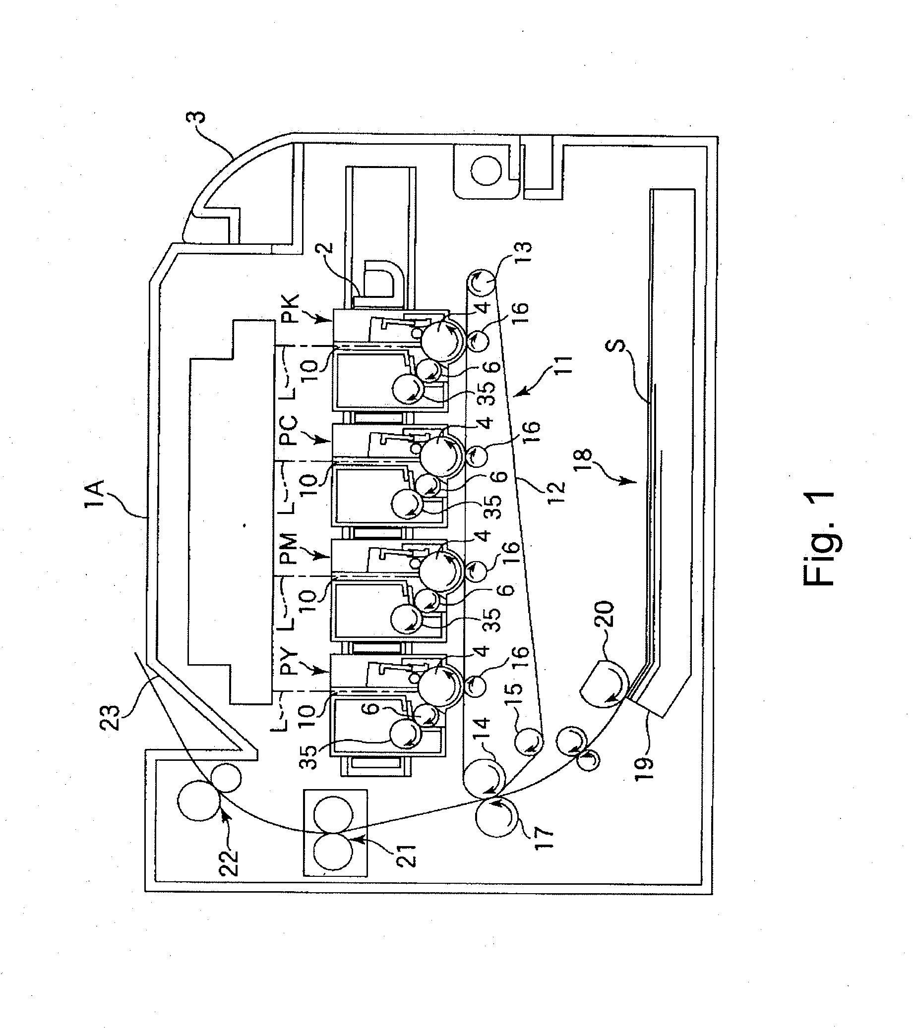
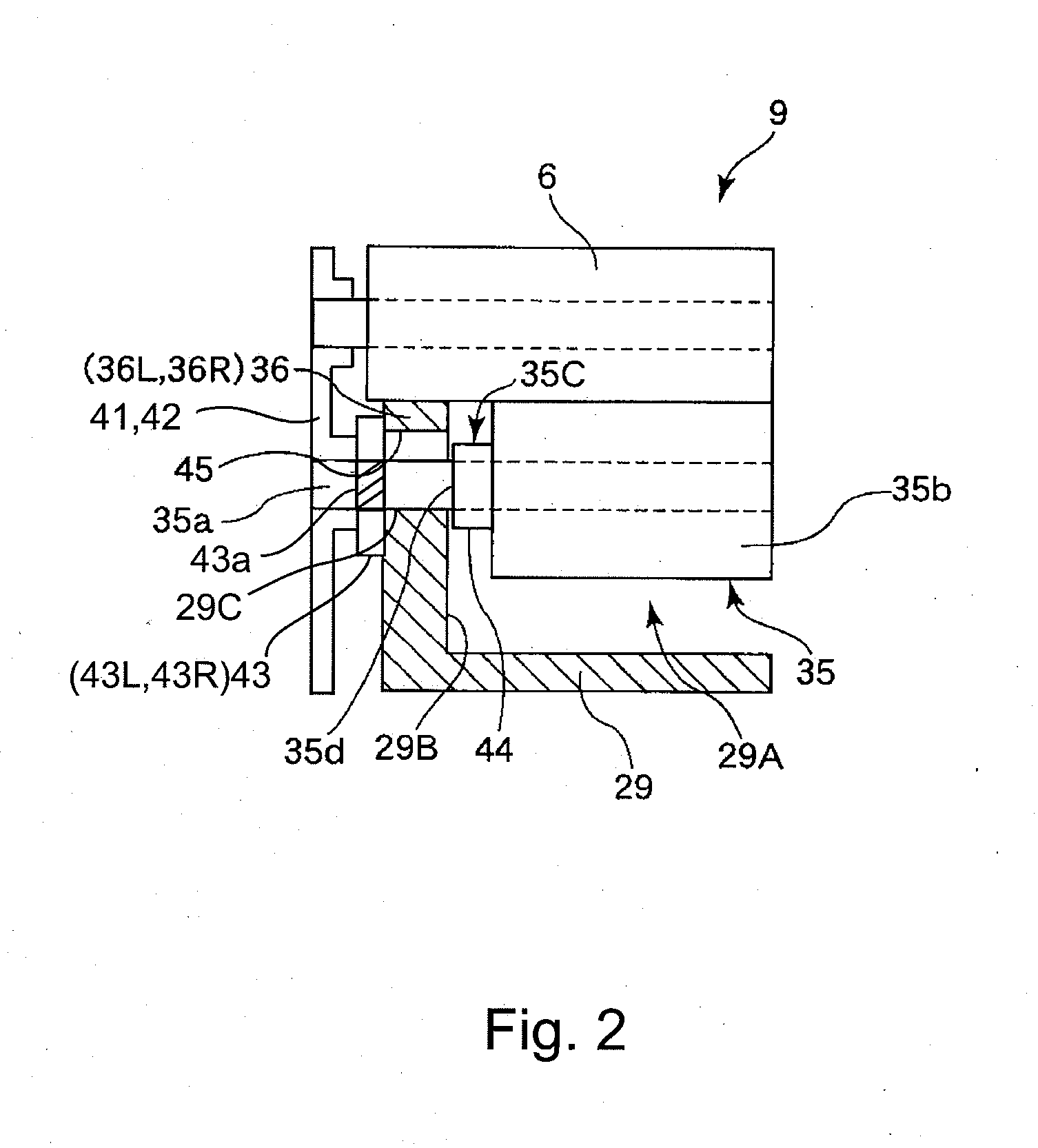
[0037]FIG. 1 show a schematic sectional structure of a color electrophotographic image forming apparatus in this embodiment in which the developing device and the process cartridge according to the present invention are mounted. This image forming apparatus 1A (hereinafter referred to as an apparatus main assembly 1A) is a four color-based full-color laser printer using the electrophotographic process and effects image formation on a recording material S. This apparatus is of a process cartridge type in which the process cartridge is detachably mountable to the apparatus main assembly 1A and a color image is formed on the recording material S.
[0038]Here, in the following description, with respect to the apparatus main assembly 1A, the side (surface) on which an apparatus opening and closing door 3 is provided is referred to as a front side (surface), and a side (surface) opposite to the front side (surface) is referred to as a rear side (surface). The left and right of the apparatus...
embodiment 2
[0074]FIG. 7 shows the developing device of the present invention in this embodiment. In this embodiment, the general structure of the developing device is the same as that in Embodiment 1, thus being omitted from description. The developing device in this embodiment is different in end portion constitution from the developing device in Embodiment 1.
[0075]That is, in this embodiment, the outer diameter of the small diameter portion 44 at the end portion 35c of the cylindrical elastic member 35b is smaller toward the extreme end of the cylindrical elastic member 35b, i.e., the end portion 35d. The outer diameter portion of the end surface 35d of the cylindrical elastic member 35b is located below the bearing surface 45 for application of the end portion seal member 36 in the developing container 29. That is, the outer diameter of the end surface 35d is made smaller than the outer diameter of the central portion so that the end surface 35d and the end portion seal Member 36 are not co...
embodiment 3
[0082]FIG. 11 shows the developing device of the present invention in this embodiment. In this embodiment, the general structure of the developing device is the same as that in Embodiment 1, thus being omitted from description. The developing device in this embodiment is different in end portion constitution from the developing device in Embodiment 1.
[0083]That is, in this embodiment, the end portion 35c (end surface 35d) of the cylindrical elastic member 35b is contacted to the opening 29A-side end portion (inner end surface 29B) of the developing container 29.
[0084]In the conventional developing device, when the end portion 35c of the cylindrical elastic member 35b, i.e., the end surface 35d was contacted to the opening 29A-side end portion (inner end portion 29B) of the developing container 29, the end surface 35d of the cylindrical elastic member 35b and the end portion seal member 36 were contacted to each other, so that there was a possibility of the occurrence of the toner le...
PUM
 Abstract
Description
Claims
Application Information
 - R&D
- Intellectual Property
- Life Sciences
- Materials
- Tech Scout
- Unparalleled Data Quality
- Higher Quality Content
- 60% Fewer Hallucinations
Browse by: Latest US Patents, China's latest patents, Technical Efficacy Thesaurus, Application Domain, Technology Topic, Popular Technical Reports.
© 2025 PatSnap. All rights reserved.Legal|Privacy policy|Modern Slavery Act Transparency Statement|Sitemap|About US| Contact US: help@patsnap.com


