
Bolt cutter

a technology of bolt cutter and handle, which is applied in the field of cylindrical object cutting devices, can solve the problems of not including a trigger mechanism attached to the handle to properly control the operation of the device, and the type of bolt cutter required a considerable amount of effort to operate and properly, and achieves the effect of convenient operation

Inactive Publication Date: 2011-08-25
VARY FR R C
View PDF13 Cites 7 Cited by
  • Summary
  • Abstract
  • Description
  • Claims
  • Application Information

AI Technical Summary

Benefits of technology

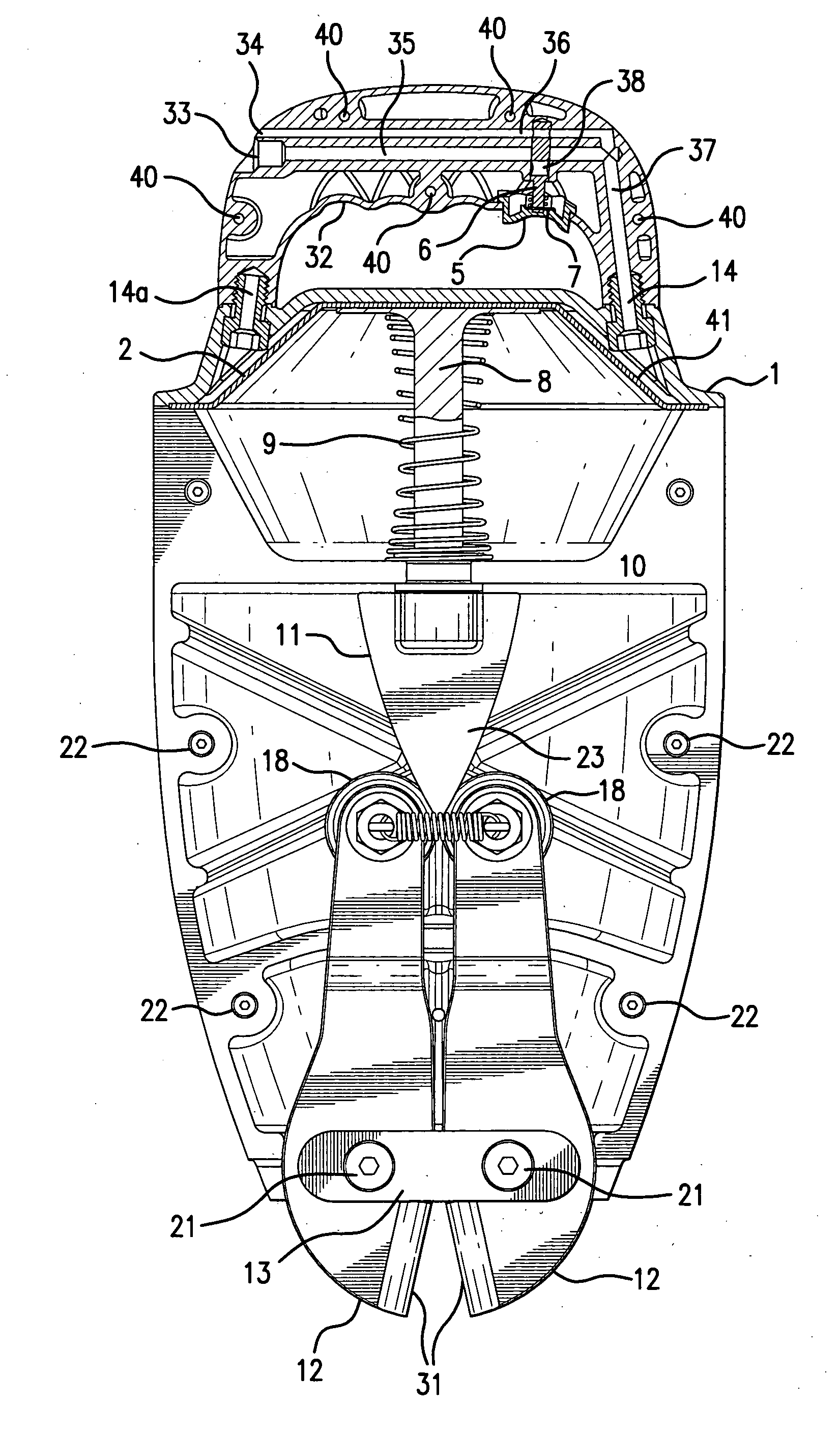
[0004]The deficiencies of the prior art are addressed by the present invention which is directed to a pneumatically operated bolt cutter which is lightweight, portable and can easily be operated. The bolt cutter includes a handle portion removably connected to a source of pressurized air at a constant pressure such as 120 PSI. Various fluid passageways in the handle would be utilized to introduce the pressurized air to the bolt cutter as well as to exhaust the air from the bolt cutter after use. A trigger provided in the handle portion is used to initiate the operation of the device. The handle is connected to a main body portion including a diaphragm, a piston and a gear cam used to force two laterally positioned jaw blades together, allowing a bolt positioned between the jaws to be cut.

Problems solved by technology

This type of bolt cutter required a considerable amount of effort to operate and to properly manipulate the cutter to adequately cut the bolt.
Additionally, this device did not include a trigger mechanism attached to a handle to properly control the operation of the device.

Method used


Image

  • Bolt cutter
  • Bolt cutter
  • Bolt cutter

Examples


Embodiment Construction

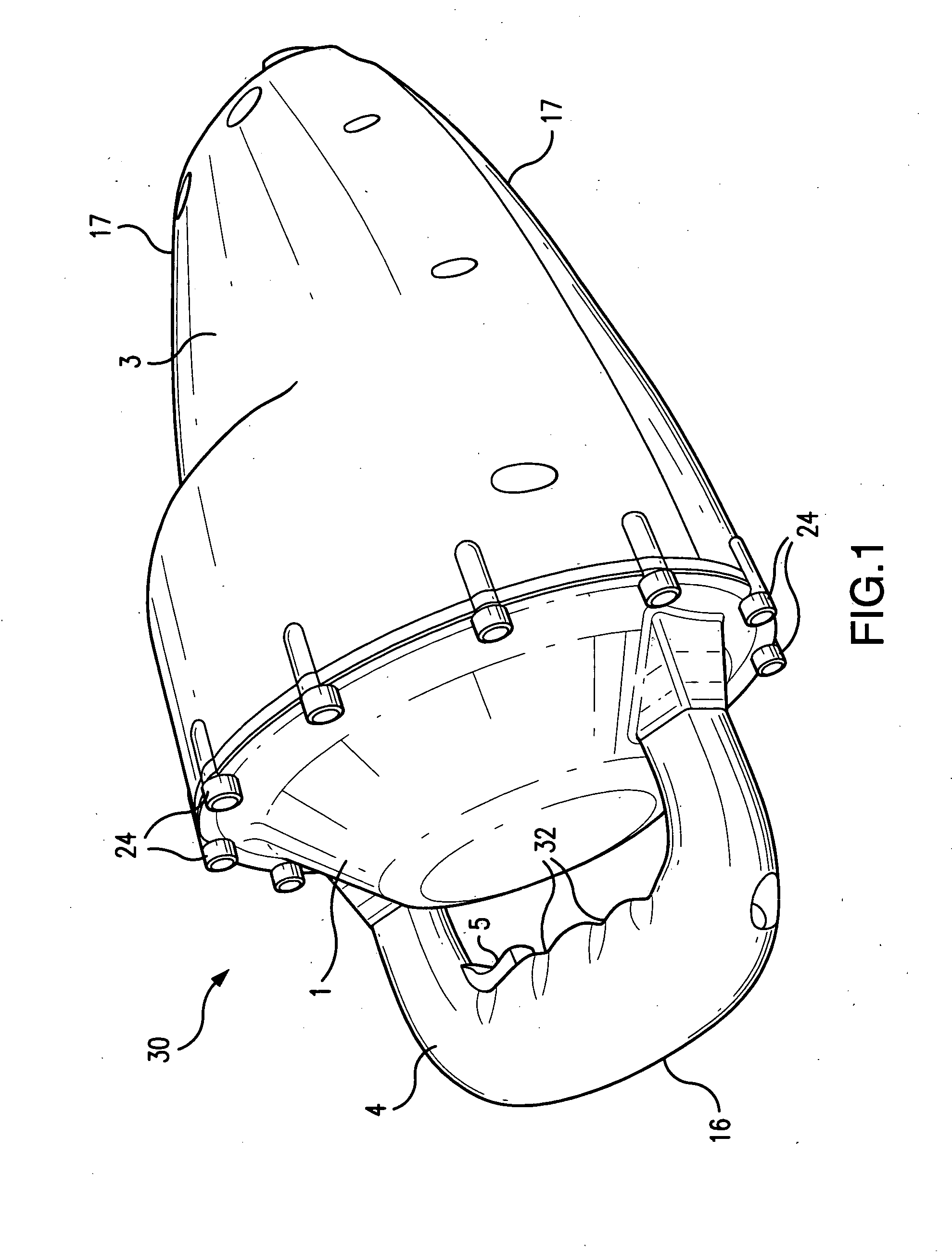
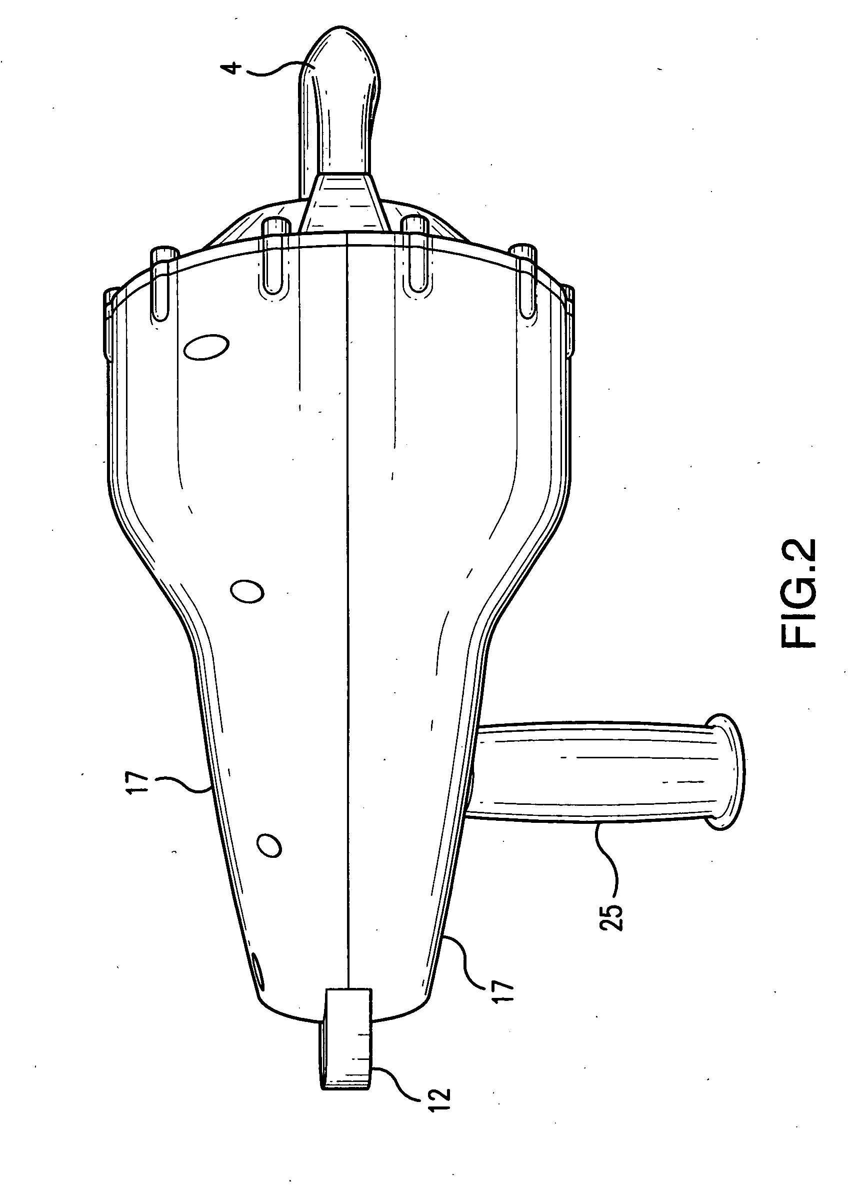
[0019]FIGS. 1-4 illustrate the present exterior configuration of the present invention 30. This configuration includes two subassemblies designated as a handle portion 4 and a main body portion 3. The main body portion also includes an end cap 1 to which the handle portion 4 is directly attached and two opposed main body covers 17. The handle portion 4 includes a handle cap 16 comprising two identical body portions which are attached to one another by a plurality of screws, bolts or similar attachments. Two jaws 12, each having a cutting surface 31 extend from the distal end of the main body portion 3.

[0020]Reference is now made to FIG. 5 in which a plurality of holes 40 are shown through which the attachment devices would pass, thereby securing the two halves of the handle portions together. The handle portion includes a trigger mechanism 5 attached proximate to a grip portion 32 having a number of indentations allowing an individual's fingers to grasp and hold the handle cap 16. T...


PUM

PropertyMeasurementUnit
mechanicalaaaaaaaaaa
forceaaaaaaaaaa
constant pressureaaaaaaaaaa

Abstract

A cutting apparatus used primarily to cut bolts or other cylindrical articles employing a source of compressed air to force a pair ofjaws together. The apparatus includes a handle provided with a trigger and a main body portion including a pair of laterally moving jaws. Compressed air will flow through the handle portion into the main body portion, thereby forcing a diaphragm downward forcing a piston to move in the direction of the jaws. A gear cam would force the proximal end of the jaw assembly outward, thereby forcing the jaws inward against one another, thereby cutting the cylindrical article.

Description

FIELD OF THE INVENTION[0001]The present invention is directed to a device for cutting a cylindrical object, such as a bolt.BACKGROUND OF THE INVENTION[0002]Prior art bolt cutters which consist of a pair of jaws used to cut the bolt traditionally utilized a mechanical lever employing large, heavy handles. Consequently, a large mechanical advantage was required to force the jaws together. This type of bolt cutter required a considerable amount of effort to operate and to properly manipulate the cutter to adequately cut the bolt.[0003]Prior art devices such as U.S. Pat. No. 5,599,227, which issued to the applicant, describe a cutting device suitable for animal dehorning which employs a pneumatically powered device. However, this device included a pair of blades, one of which moved downward to a second blade to dehorn the animal. Additionally, this device did not include a trigger mechanism attached to a handle to properly control the operation of the device.SUMMARY OF THE INVENTION[000...

Claims


Application Information

Patent Timeline
Patent Type & Authority Applications(United States)
IPC IPC(8): B26B17/00
CPCB26B17/02B23D29/007
Inventor VARY, FRANK R. C.
Owner VARY FR R C
Learn More