Burner arrangement

a technology for burners and supports, applied in the direction of combustion types, machines/engines, lighting and heating apparatuses, etc., can solve the problems of high cost, and achieve the effects of reducing weight and cost, reducing material strength of supports, and simplifying the machining of supports

Active Publication Date: 2011-08-25
SIEMENS ENERGY GLOBAL GMBH & CO KG
View PDF10 Cites 5 Cited by
  • Summary
  • Abstract
  • Description
  • Claims
  • Application Information

AI Technical Summary

Benefits of technology

[0014]Thus a distribution channel in the support can be dispensed with. As a result the material strength of the support can be reduced, as a result of which weight and costs are saved. Additionally the demands on the installation space for the burner arrangement in the region of the side of the support facing away from the fuel nozzles are less stringent compared to the prior art. Overall the machining of the support is also simplified.
[0015]Remote from the support at least one distribution channel is provided, which supplies the extension parts remote from the support with fuel. Since the distribution channels are now located remote from the support and also—unlike the original distribution channels—are not directly in contact with hot gas, the distribution channels can now be made from lower-cost material. As a result a significant cost saving can be achieved. This means that the fuel is already distributed upstream (viewed in the in direction of flow) of the support and is not split between the channels downstream of the support.

Problems solved by technology

These are however very expensive.

Method used


Image

  • Burner arrangement
  • Burner arrangement
  • Burner arrangement

Examples


Embodiment Construction

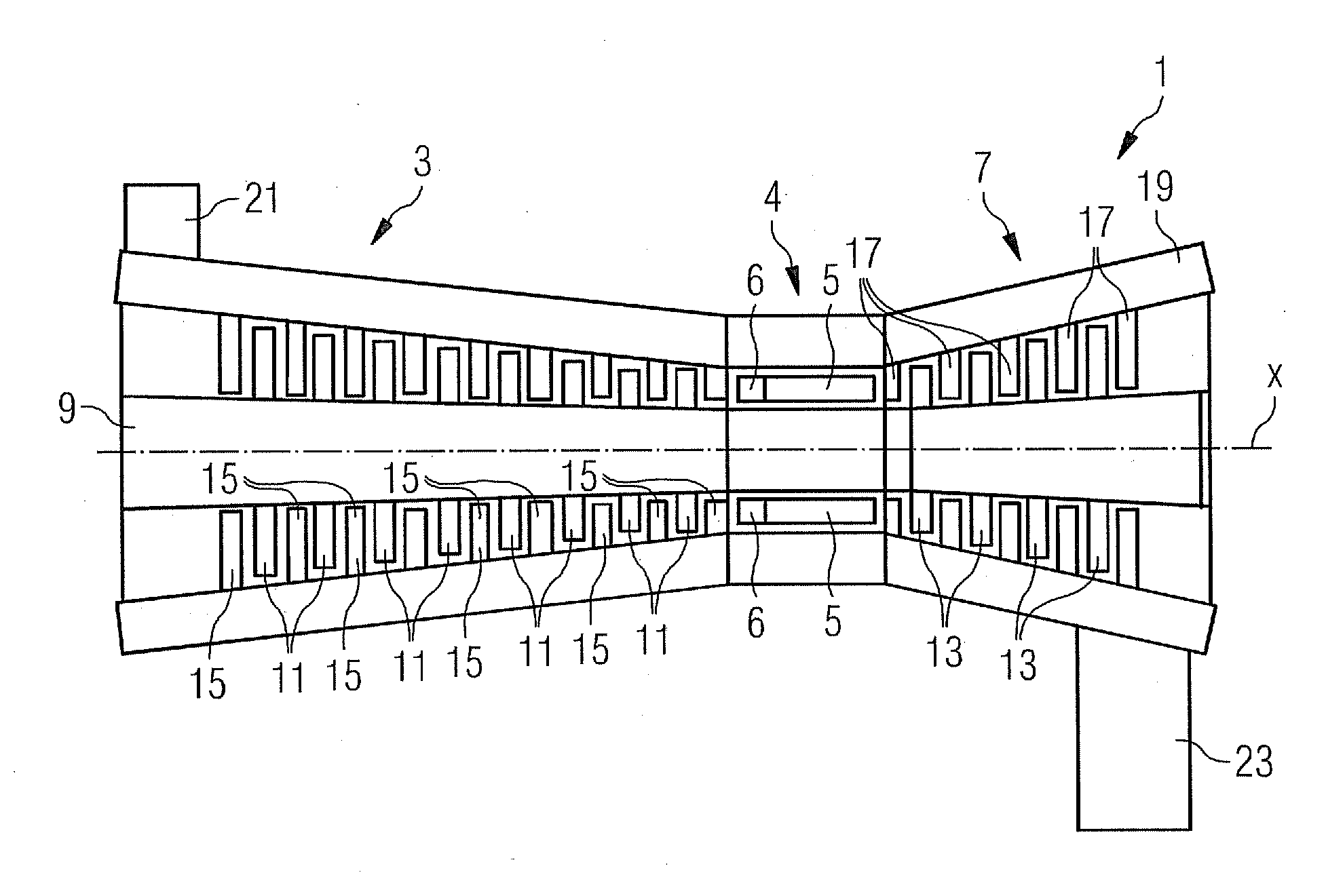
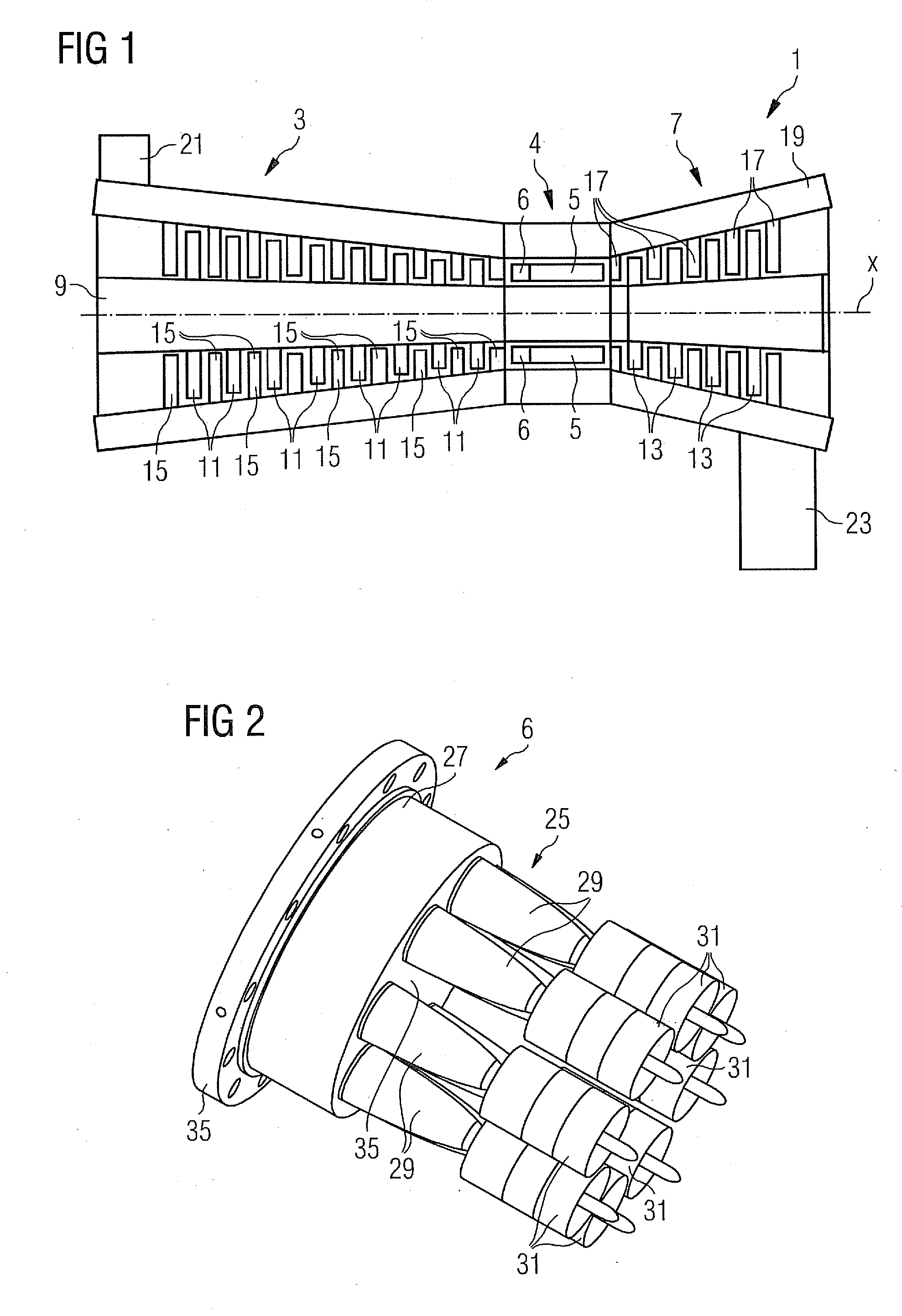
[0037]The structure and function of a gas turbine are explained below on the basis of FIG. 1, which shows a highly diagrammatic sectional view of a gas turbine. The gas turbine 1 includes a compressor section 3, a combustion section 4 which in the present exemplary embodiment includes a plurality of pipe combustion chambers 5 with burners 6 arranged thereon, but which can fundamentally also include an annular combustion chamber, and a turbine section 7. A rotor 9 extends through all sections and in the compressor section 3 supports compressor blade rings 11 and in the turbine section 7 turbine blade rings 13. Rings composed of compressor guide vanes 15 or rings composed of turbine guide vanes 17 are arranged between adjacent compressor blade rings 11 and between adjacent turbine blade rings 13, said rings extending out radially from a housing 19 of the gas turbine 1 in the direction of the rotor 9.

[0038]During operation of the gas turbine 1 air is sucked in through an air inlet 21 i...


PUM


Abstract

A burner arrangement is provided. The burner arrangement includes a support and at least two fuel nozzles attached to the support in the direction of flow, with each fuel nozzle including a support-side section which includes a contact surface on the support side with which it rests on a supporting surface of the support, with at least two fuel nozzle tips embodied in one piece extending out from the support-side section in the direction of flow and the support-side contact surface including at least two extension parts projecting in the direction of the support, with the extension parts each embodying a channel through which fuel is fed in each case to the fuel nozzle tips through passages which are arranged in the support-side contact surface of the support-side section.

Description

CROSS REFERENCE TO RELATED APPLICATIONS[0001]This application claims priority of European Patent Office application No. 10154116 EP filed Feb. 19, 2010, which is incorporated by reference herein in its entirety.FIELD OF INVENTION[0002]The present invention relates to a burner arrangement and in particular to a burner arrangement for gas turbines.BACKGROUND OF INVENTION[0003]Essential component parts of a gas turbine include a compressor, a turbine with rotor blades and at least one combustion chamber. The rotor blades of the turbine are arranged as rotor blade rings on a shaft which in the main extends through the entire gas turbine, and is connected to a consumer load, for instance a generator for power generation. The shaft provided with the rotor blades is also called a (turbine) rotor. Between the rotor blade rings are guide vane rings, which act as nozzles to conduct the working medium through the turbine.[0004]During operation of the gas turbine compressed air from the compres...

Claims


Application Information

Patent Timeline
Patent Type & Authority Applications(United States)
IPC IPC(8): F23R3/28F02M61/18
CPCF23C2900/07021F23R2900/00018F23R3/283F23D23/00
Inventor BOTTCHER, ANDREASFOX, TIMOTHY A.GRIEB, THOMASKRIEGER, TOBIASRAMIER, STEPHEN A.
Owner SIEMENS ENERGY GLOBAL GMBH & CO KG
Why Eureka
Try Eureka