Solar heating system with overheating protection

Active Publication Date: 2011-08-25
TRATHOM CORP
View PDF8 Cites 24 Cited by
  • Summary
  • Abstract
  • Description
  • Claims
  • Application Information

AI Technical Summary

Benefits of technology

[0017]In one broad aspect of the invention, apparatus for maximizing thermal energy collection in a solar collection system independent from the electric utility grid or external energy provider comprises: one or more solar collectors; a heat exchange circuit having fluid therein and being thermally connected between the one or more solar collectors and a point of use; a solar powered pump for substantially continuously pumping the fluid through the heat exchange circuit during solar energy collection; a heat dissipater fluidly connected to the heat exchange circuit and having an inlet upstream from the one or more solar collectors and an outlet downstream from the one or more solar collectors; and a valve positioned downstream from the heat dissipater which, when closed in response to a condition being at or below a maximum preset operating condition, prevents fluid from entering the heat dissipater; and when opened in response to the condition exceeding the maximum preset operating condition, permits at least a portion of the fluid in the heat exchange circuit to bypass the one or more solar collectors to flow through the heat dissipater for cooling the at least a portion of the fluid, the cooled fluid being

Problems solved by technology

Combined systems are generally not practical in colder climates as the hot water storage tank is cooled by the cold ambient air.
Direct systems are typically prone to scaling of the collector as a result of the domestic water passing therethrough.
Solar energy can only be harnessed when the sun is shining and some of the heat gained during the day is lost if the potable water or working fluid continues to circulate during nights or during periods of low solar potential.
A significant issue with solar water heating systems is how to mitigate excessive heat.
If means for releasing pressure are not provided, excess heat leads to boiling of the working fluid and the resultant pressure increases will rupture the piping or solar collector.
Often systems are deliberately under-sized to avoid the overheating challenge.
Thus, it is clear in these cases that solar collection is not maximized.
Applicant believes it is likely that there will be insufficient impetus for thermosiphon within the complex piping of Torrens, resulting in the possibility of overheating of the fluids therein despite the heat dissipation circuit.
The Torrens system is particularly unsuitable for use where ambient temperatures fall below freezing as it is a direct system.
In cases of peak insola

Method used


Image

  • Solar heating system with overheating protection
  • Solar heating system with overheating protection
  • Solar heating system with overheating protection

Examples


example

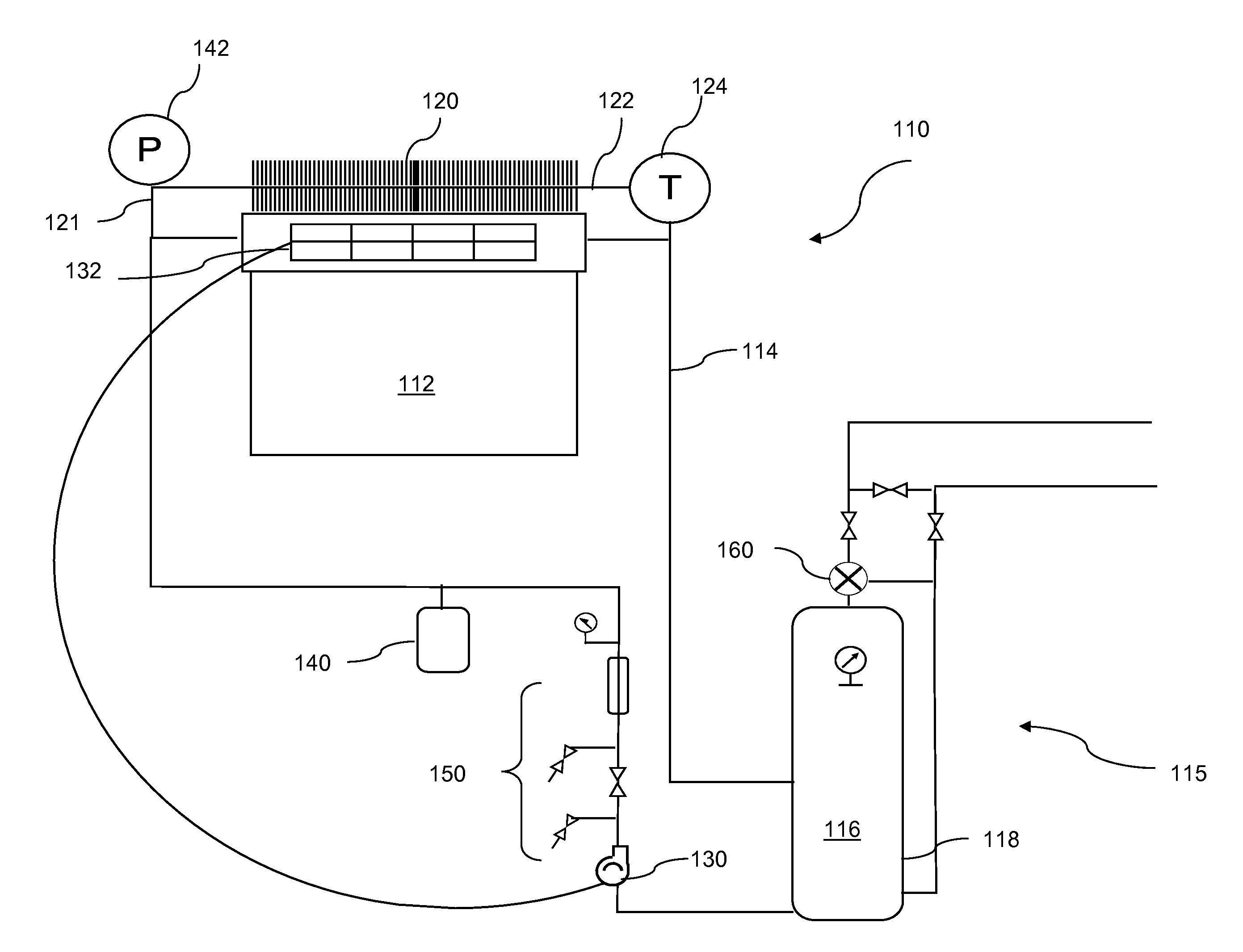
[0054]In an indirect solar water heater system, according to an embodiment of the invention and as shown schematically in FIG. 2A, a solar collector 112 comprising 30, 58 mm×1800 mm evacuated tubes, rated at a maximum thermal output of about 7400 BTU per hour, available from Jiangsu Sunrain Co. Ltd., was mounted to the roof of a structure. The collector assembly was mounted at an angle of about 70 degrees from horizontal to ensure solar gain was maximized during the winter and minimized during the summer as is known in the art.

[0055]The solar collector 112 was thermally and fluidly connected to a 300 L (80 USG) hot water tank 118 located within the structure, using ¾″ cross-linked polyethylene (PEX) pipe and fittings, for forming the heat exchange circuit 114, through which a working fluid was circulated. All piping in the system was insulated to reduce energy losses.

[0056]The working fluid for circulation through the heat exchange circuit comprised distilled water mixed at about 50...


PUM


Abstract

A simple solar heating system incorporates a heat dissipater into a heat exchange circuit for bypassing solar collectors when either the temperature or the pressure in the heat exchange circuit exceeds preset limits. In the absence of electric controllers, fluid in the heat exchange circuit is caused to bypass the solar collectors using a valve which is controlled by either the temperature or pressure of the fluid. A solar photovoltaic panel energizes a circulating pump for increasing the rate of pumping as more solar energy is available at the PV panel and decreasing the rate as solar energy decreases.

Description

FIELD OF THE INVENTION[0001]Embodiments of the invention relate to solar heating systems and more particularly to systems for use with solar water heaters that are independent of the electrical utility grid and that substantially prevent overheating of fluids circulating therethrough.BACKGROUND OF THE INVENTION[0002]Collection of solar energy for use in heating fluids, such as water, is a well known concept with rudimentary systems originating in ancient times. Modern solar heating systems typically incorporate a solar collector that converts the sun's energy to thermal energy and utilize a variety of means to transfer the collected thermal energy into the fluid to be heated, such as for residential, commercial or industrial heating applications.[0003]Solar water heaters may be combined systems or distributed systems. In the case of a combined system, a domestic water storage tank is typically mounted directly to the solar collector. Combined systems are generally not practical in c...

Claims


Application Information

Patent Timeline
IPC IPC(8): F24J2/40F24J2/04F24J2/00F24D18/00F24S10/75F24S90/00
CPCF24D11/003F24D19/0095F24H2240/09Y02E10/40F24J2/4625F24J2/463Y02B10/20F24J2/42F24S90/00F24S40/55F24S40/58F24D2103/13F24D18/00F24D2101/40
Inventor JACKMAN, THOMAS J.
Owner TRATHOM CORP
Why Eureka
Try Eureka