Aircraft fairing

a technology for fairings and aircraft, applied in the field of fairings, can solve the problems of limiting the lift that the inner region of the wing generates, and undesirable shocks, and achieve the effect of reducing the amount of li

Active Publication Date: 2011-08-25
AIRBUS OPERATIONS LTD
View PDF11 Cites 14 Cited by
  • Summary
  • Abstract
  • Description
  • Claims
  • Application Information

AI Technical Summary

Benefits of technology

[0016]An aircraft provided with a shock control fairing according to an embodiment of the invention has been found to generate a number of advantageous effects on the flow field surrounding the inner wing and the junction. Providing a fairing having a maximum area at a location which is substantially proximal to a location on the upper surface of the aircraft wing at which a shock would be expected to develop without the fairing present is thought to modify the pressure gradients that arise in the vicinity of the junction during flight.
[0017]As will be understood by the person skilled in the art, the spanwise direction extends from the fuselage to the wing tip, and is perpendicular to the longitudinal direction such that the wing tip is at 100% span and the longitudinal centre-line of the aircraft is at 0% span.
[0018]As will also be understood by the person skilled in the art, the wing root chord is the value of the chord at the wing root. On many aircraft, the geometry of the wing and / or the fuselage may be such that the spanwise position of the wing root varies between the leading edge and the trailing edge of the wing. In such circumstances, it will be understood that the wing root chord refers to the chord at the spanwise location on the wing that coincides with the point on the junction lying furthest from the centre-line of the aircraft.
[0019]On a typical transonic passenger aircraft wing a significant shock may be found to occur proximal to a mid chord region of the wing root junction. Accordingly in some embodiments, the shock control fairing is arranged such that, when mounted to an aircraft, with its length extending along a chordwise direction of the aircraft wing root, the cross-sectional profile has a maximum area in a mid-chord region of the wing root. For example, the cross-sectional profile may have a maximum area located between 20% wing root chord and 70% wing root chord. In some embodiments the cross-sectional profile may have a maximum area located between 30% wing root chord and 50% wing root chord.
[0020]The fairing may be blended at one end, and more preferably both ends, with an aircraft belly fairing.
[0021]The fairing may have an upper surface arranged to extend, when mounted to an aircraft, between an aircraft fuselage and an upper surface of an aircraft wing. Part of the surface may be substantially flat or concave. At least part of the surface may be convex in the a spanwise plane and / or in a chordwise plane.

Problems solved by technology

The shock may be undesirable for a number of reasons.
For example, the shock can cause considerable wave drag and may also limit the amount of lift that the inner region of the wing generates.

Method used


Image

  • Aircraft fairing
  • Aircraft fairing
  • Aircraft fairing

Examples


first embodiment

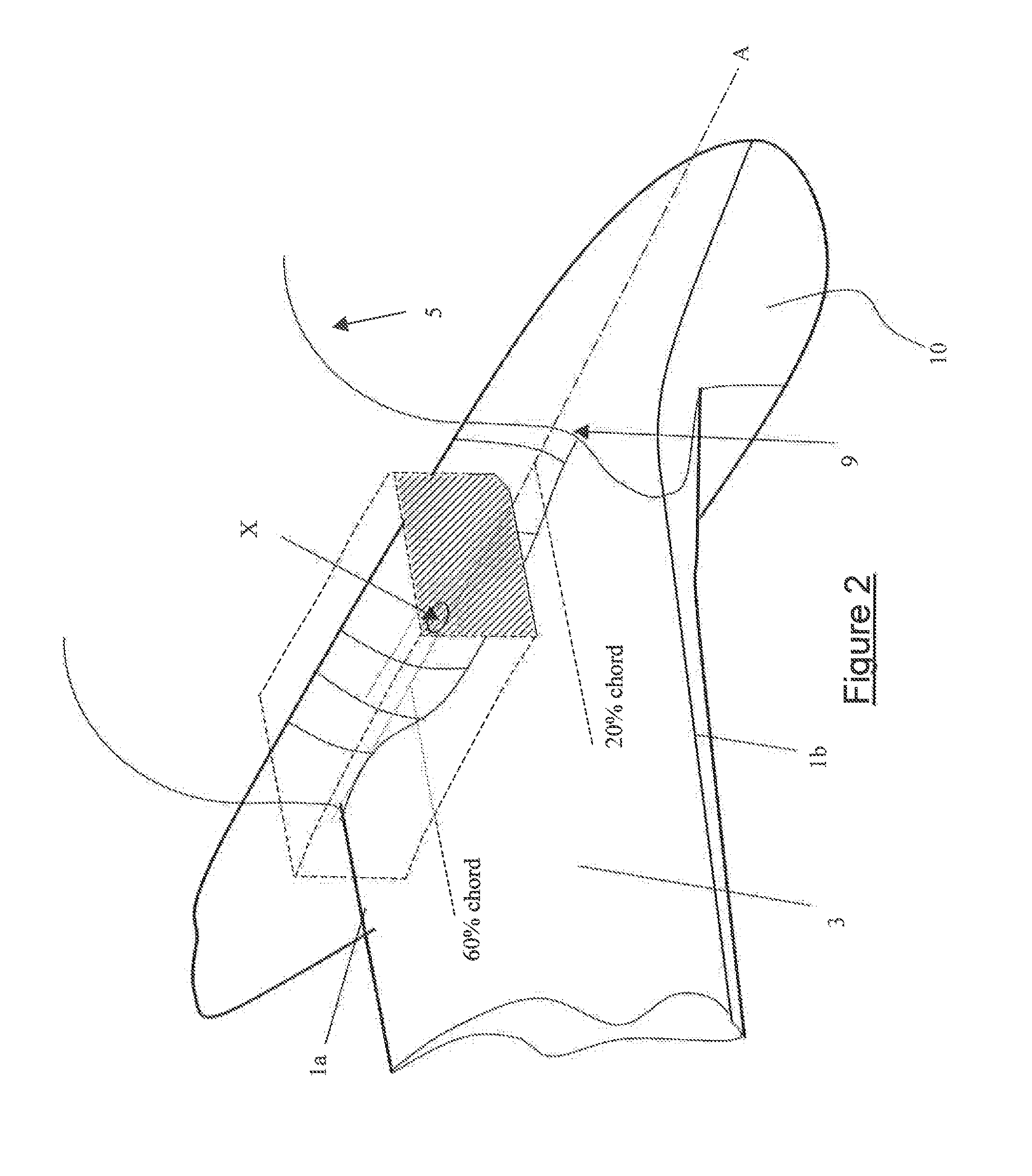
[0051]FIG. 2 is a perspective view of part of the aircraft according to the invention;

[0052]FIG. 3 is a front view of part of an aircraft according to a first embodiment of the present invention;

[0053]FIGS. 4a and 4b are schematic plan views of the inner wing region showing the typical shock pattern of an aircraft fitted with a known conventional wing root fairing and part of the aircraft according to an embodiment of the invention;

[0054]FIGS. 5a to 5c are plots showing the chordwise pressure distribution at three stations along the wing of the aircraft according to the first embodiment of the invention;

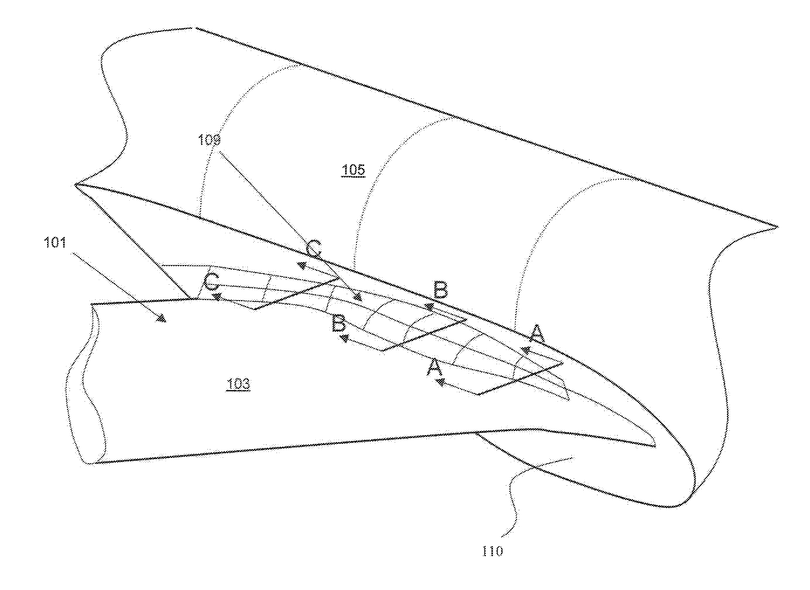
[0055]FIG. 6 is a perspective view of part of an aircraft according to an embodiment of the invention and

[0056]FIG. 7 illustrates the variation of the cross-sectional area of a shock control fairing according to an embodiment of the invention and a traditional wing root fairing.

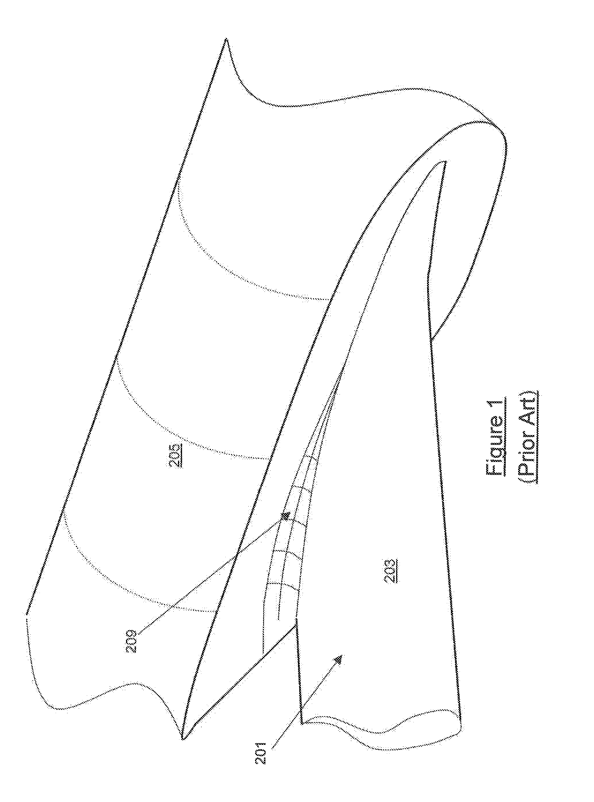
[0057]As described above FIG. 1 represents a conventional wing root fairing. The skilled person in the art ...

second embodiment

[0072]FIG. 6 is a perspective view of part of an aircraft according to the invention. The aircraft comprises a wing 101 having an upper surface 103 which forms as junction with the fuselage 105 at the wing root. The aircraft also comprises a fairing 109 (shown in FIG. 6 as a computer generated mesh) located on the upper surface 103 of the wing 101 at the junction.

[0073]FIG. 7 represents a comparison of the variation of the cross-sectional area of a shock control fairing according to the embodiment of FIG. 6 relative to a conventional wing root fairing. The cross-sectional area of the conventional fairing (dashed line) can be seen to increase from a minimum at the wing leading edge (0% root chord) to a maximum at the wing trailing edge (100% root chord). The fairing according to an embodiment the invention has a maximum cross-sectional area in the mid-chord region with the area increasing along the length of the wing root from the trailing edge to the mid-chord region and then decrea...


PUM

PropertyMeasurementUnit
dry weightaaaaaaaaaa
heightaaaaaaaaaa

Abstract

A shock control fairing for mounting a junction between adjoining aircraft surfaces. The fairing has a cross-sectional profile which varies along the length of the fairing. The cross-sectional profile of the fairing has a maximum area at a location which, when mounted to an aircraft, is substantially proximal to a location on the surface of the aircraft at which a shock would be expected to develop without the fairing.

Description

FIELD OF THE INVENTION[0001]The present invention relates to a fairing, and more particularly to a shock control fairing for mounting on the upper surface of a junction between an aircraft fuselage and wing.BACKGROUND TO THE INVENTION[0002]As shown in FIG. 1, many aircraft include a fairing at the upper surface 203 of a junction between the aircraft fuselage 205 and wing 201 (i.e. the upper surface of the wing root). One function of such fairings is to reduce or eliminate separation of the airflow in the region of the junction and thereby reduce viscous drag on the aircraft.[0003]A typical prior art wing root fairing 209 is in the form of a concave, wedge-shaped fillet (the upper surface of the which is represented by the mesh in FIG. 1). The fillet starts at a mid-chord region of the wing root and extends to a maximum cross-sectional area at, or slightly aft of, the trailing edge of the wing root. These known fairings are referred to herein as a “conventional wing root fairing”.[00...

Claims


Application Information

Patent Timeline
Patent Type & Authority Applications(United States)
IPC IPC(8): B64C7/00B64C23/00G06F17/50B23P17/04
CPCB64C7/00Y10T29/49826B64C23/04
Inventor LYONS, NEIL JOHN
Owner AIRBUS OPERATIONS LTD
Why Eureka
Try Eureka