Elongated structure for movable section
a technology of movable sections and elongated structures, which is applied in the direction of insulated conductors, cables, conductors, etc., can solve the problems of disordered movement of cables and tubes, etc., and achieve the effect of enlargement of attachment strength
- Summary
- Abstract
- Description
- Claims
- Application Information
AI Technical Summary
Benefits of technology
Problems solved by technology
Method used
Image
Examples
first embodiment
of the Invention
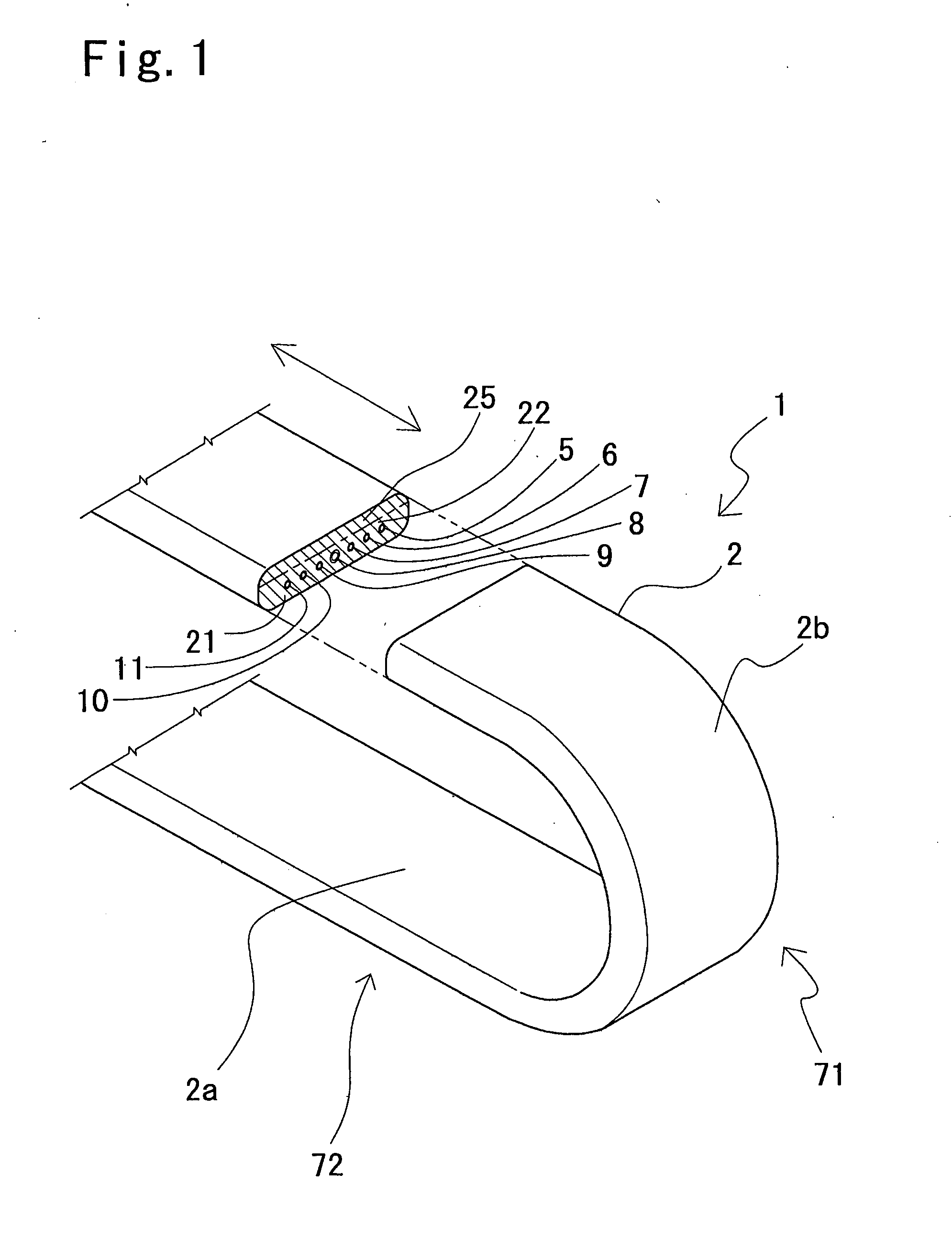
With reference to FIG. 1, an elongated structure for a movable section according to the first embodiment of the present invention will now be explained below.
In FIG. 1, the elongated structure 1 for the movable section includes a sheath member 2 which is formed as an elongated flexible member, and a plurality of operational flexible linear elements 5, 6, 7, 8, 9, 10 and 11 which are provided in the sheath member 2 so as to be extend from one end of the sheath member 2 from the other end thereof, and through which operational factors are transmitted.
The aforesaid sheath member 2 has an elongated flat belt-like configuration having a suitable thickness, and the operational linear elements 5, 6, 7, 8, 9, 10 and 11, such as conductor wires, tubes and so on for transmitting the operational factors such as electricity, air and so on, are arranged widthwise in the sheath member 2 in parallel so as to be spaced away from each other. The sheath member 2 is formed of a synthet...
second embodiment
of the Invention
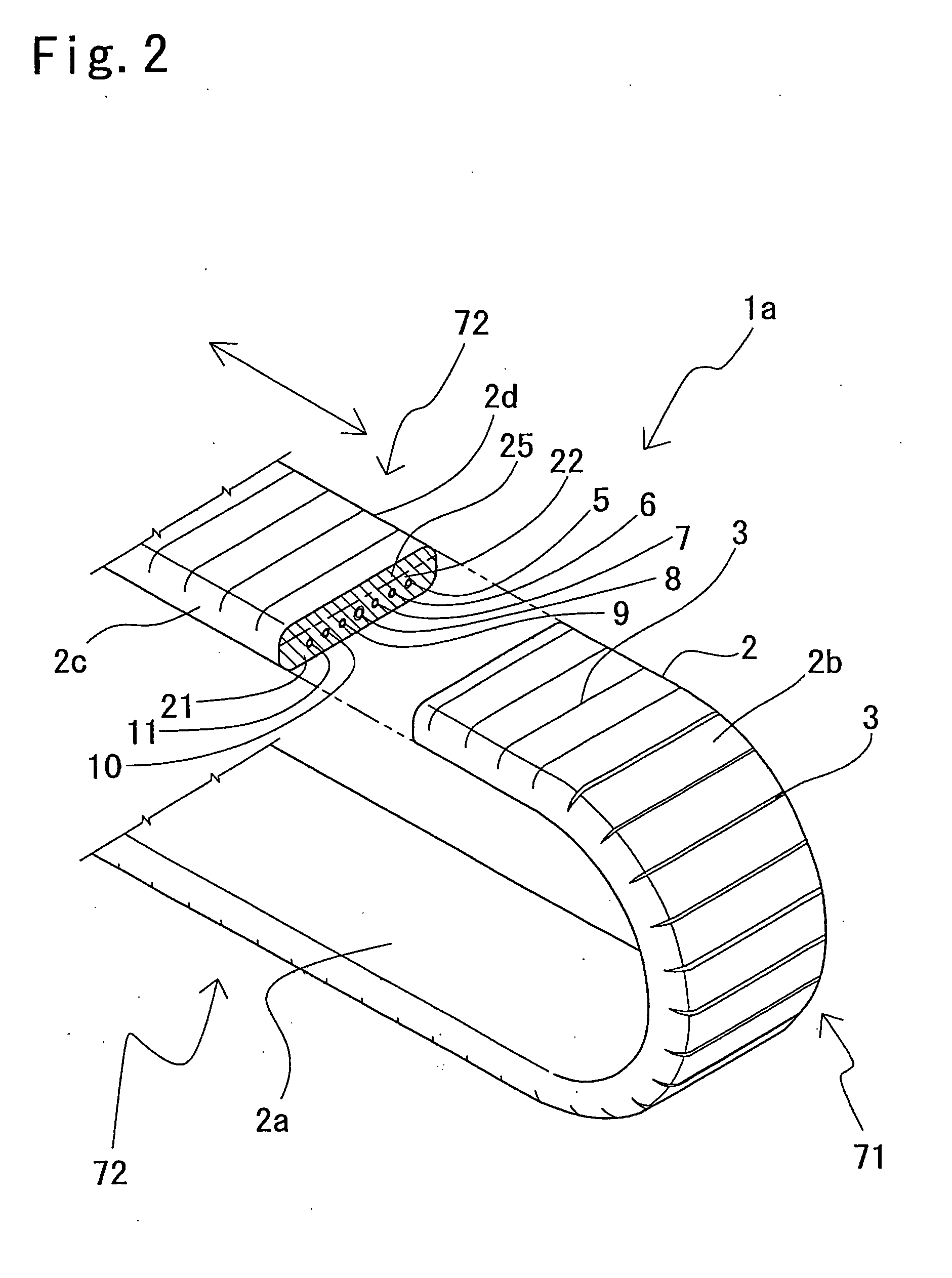
With reference FIG. 2 a second embodiment of the present invention will now be explained. As shown in FIG. 2, in an elongated structure 1a for a movable section, a plurality of slits 3 are provided in a sheath member 2. Note, in FIG. 2, the same references as in FIG. 1 indicate the corresponding elements, and explanations of these elements are omitted.
As shown in FIG. 2, the plurality of slits 3 are formed in a surface 2b of an outer region of the sheath member 2, which is defined as an outer surface, at given regular intervals in a longitudinal direction of the sheath member 2 so as to be extended from one side face 2c of the sheath member 2 to the other side face 2d through the outer surface 2b thereof. Some of the slits 2 are opened in a U-shaped bent portion 71 of the elongated structure 1a for the movable section, and the remaining slits 3 are closed in linear portions 72 thereof except for U-shaped bent portion 71. Thus, when forces for bending the elongated st...
third embodiment
of the Invention
With reference to FIG. 3, a third embodiment of the present invention will now be explained. As shown in FIG. 3, an elongated structure 1b for a movable section has a flat belt-like configuration in which a plurality of sheath members 20 are arranged in parallel and securely attached to each other.
As shown in FIG. 3, each of the sheath members 20 has generally-oval end faces, and these sheath members 20 are arranged so that the major axes in the generally-oval end faces are parallel to each other. Operational flexible linear elements 5, 6, 7, 8, 9, 10 and 11 are provided in the respective sheath members 20 so that the center of each of the operational linear elements 5, 6, 7, 8, 9, 10 and 11 is offset from the center of the major axis of a corresponding sheath member 2 toward one end 20a of the major axis by a predetermined distance. Thus, a thickness of an outer region 22, which is measured from the other ends 20b of the major axes, defined as the outer ends, to the...
PUM
 Abstract
Description
Claims
Application Information
 - R&D
- Intellectual Property
- Life Sciences
- Materials
- Tech Scout
- Unparalleled Data Quality
- Higher Quality Content
- 60% Fewer Hallucinations
Browse by: Latest US Patents, China's latest patents, Technical Efficacy Thesaurus, Application Domain, Technology Topic, Popular Technical Reports.
© 2025 PatSnap. All rights reserved.Legal|Privacy policy|Modern Slavery Act Transparency Statement|Sitemap|About US| Contact US: help@patsnap.com


