Transmitter and receiver synchronization for wireless telemetry systems

a wireless telemetry and transmitter technology, applied in the field of telemetry systems, can solve the problems of difficult cable connection, inconvenient use, and difficulty in providing such communication using a cable, and achieve the effect of lowering the bit rate of the transmitted signal

a wireless telemetry and transmitter technology, applied in the field of telemetry systems, can solve the problems of difficult cable connection, inconvenient use, and difficulty in providing such communication using a cable, and achieve the effect of lowering the bit rate of the transmitted signal

US20110205080A1Inactive Publication Date: 2011-08-25SCHLUMBERGER TECH CORP

Image

  • Transmitter and receiver synchronization for wireless telemetry systems
  • Transmitter and receiver synchronization for wireless telemetry systems
  • Transmitter and receiver synchronization for wireless telemetry systems

Examples


Embodiment Construction

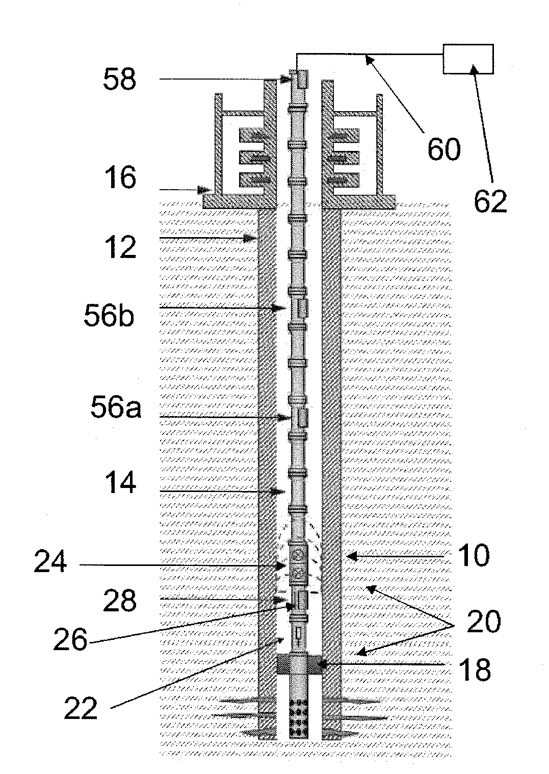
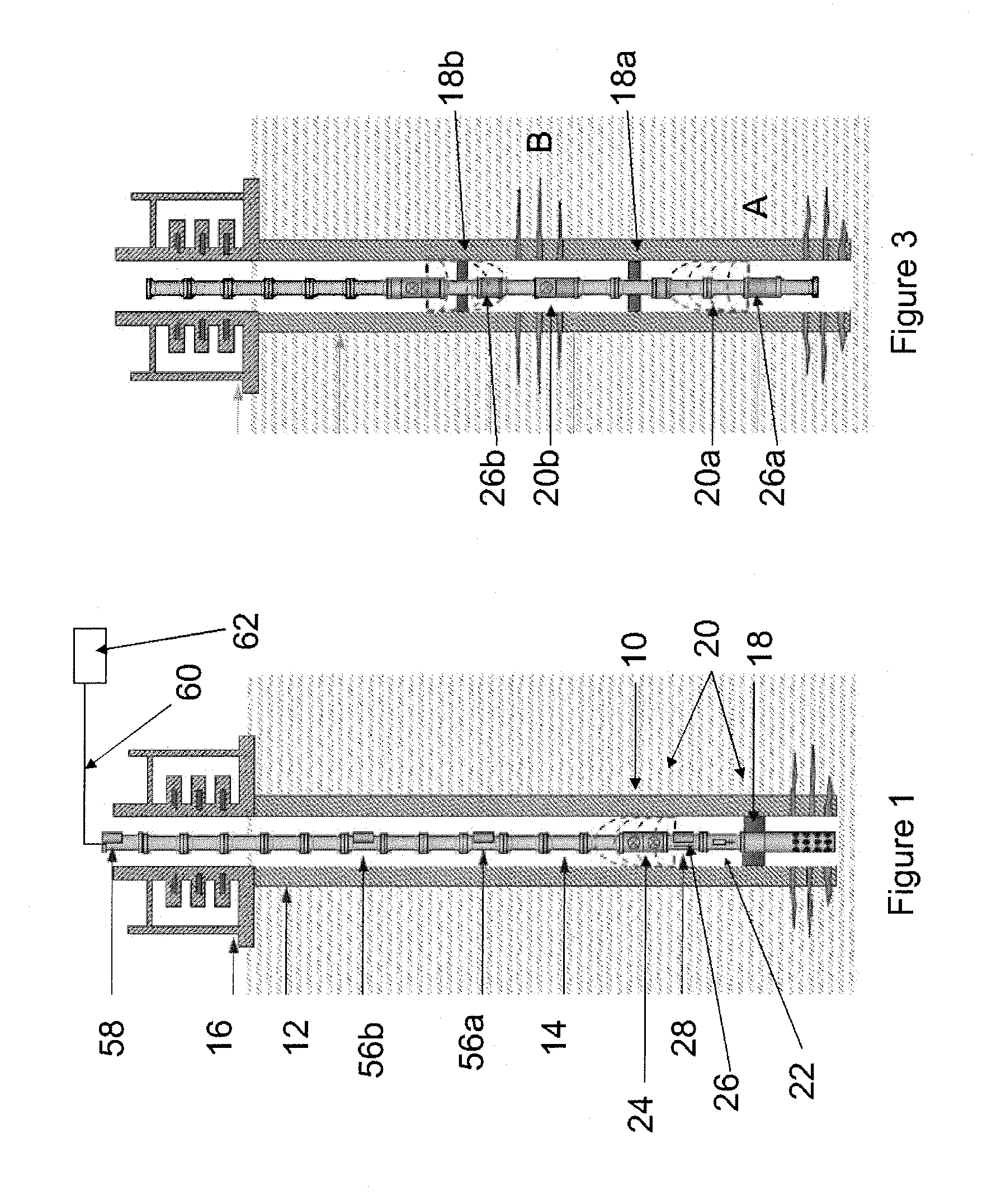
[0051]The present invention is particularly applicable to testing installations such as are used in oil and gas wells or the like. FIG. 1 shows a schematic view of such a system. Once the well has been drilled through a formation, the drill string can be used to perform tests, and determine various properties of the formation though which the well has been drilled. In the example of FIG. 1, the well 10 has been lined with a steel casing 12 (cased hole) in the conventional manner, although similar systems can be used in unlined (open hole) environments. In order to test the formations, it is preferable to place testing apparatus in the well close to the regions to be tested, to be able to isolate sections or intervals of the well, and to convey fluids from the regions of interest to the surface. This is commonly done using a jointed tubular drill pipe, drill string, production tubing, or the like (collectively, tubing 14) which extends from the well-head equipment 16 at the surface (...


PUM


Abstract

A method and system are presented for transmitting data along tubing in a borehole, comprising generating an acoustic signal using a transmitter at a first location on the tubing, and receiving the acoustic signal at a receiver at a second location on the tubing. The method and system further comprise: (i) generating the acoustic signal at the transmitter at a first frequency and bit rate; (ii) receiving the acoustic signal at the first frequency at the receiver and attempting to synchronise the receiver at the first frequency, and (iiia) if the synchronization is successful, continuing to transmit the acoustic signal so as to pass the data from the transmitter to the receiver; or (iiib) if the synchronization is unsuccessful, adjusting the frequency and / or bit rate of the signal and repeating steps (i)-(iii) on the basis of the adjusted signal.

Description

CROSS-REFERENCE TO RELATED APPLICATION[0001]The present application is based on and claims priority to European Patent Application No. EP08162855, filed Aug. 22, 2008.TECHNICAL FIELD[0002]The present invention relates to telemetry systems for use with installations in oil and gas wells or the like. In particular, the present invention relates to the synchronization of transmitters and receivers for transmitting data and control signals between a location down a borehole and the surface, or between downhole locations themselves.BACKGROUND ART[0003]One of the more difficult problems associated with any borehole is to communicate measured data between one or more locations down a borehole and the surface, or between downhole locations themselves. For example, in the oil and gas industry it is desirable to communicate data generated downhole to the surface during operations such as drilling, perforating, fracturing, and drill stem or well testing; and during production operations such a...

Claims


Application Information

Patent Timeline
25 Aug 2011
Publication
US20110205080A1
IPC
G01V3/00; E21B47/12; E21B47/16
CPC
E21B47/16; E21B47/122; E21B47/13
Inventors
MILLOT, GUILLAUME; LEMENAGER, ERWANN