

Lighting device, display device and television receiver
a technology of display device and light source, which is applied in the direction of lighting and heating equipment, television systems, instruments, etc., to achieve the effect of easy attainment of uniform light brightness
- Summary
- Abstract
- Description
- Claims
- Application Information
AI Technical Summary
Benefits of technology
Problems solved by technology
Method used
Image

Examples
first embodiment
[0046]The first embodiment of the present invention will be explained with reference to FIGS. 1 to 7.
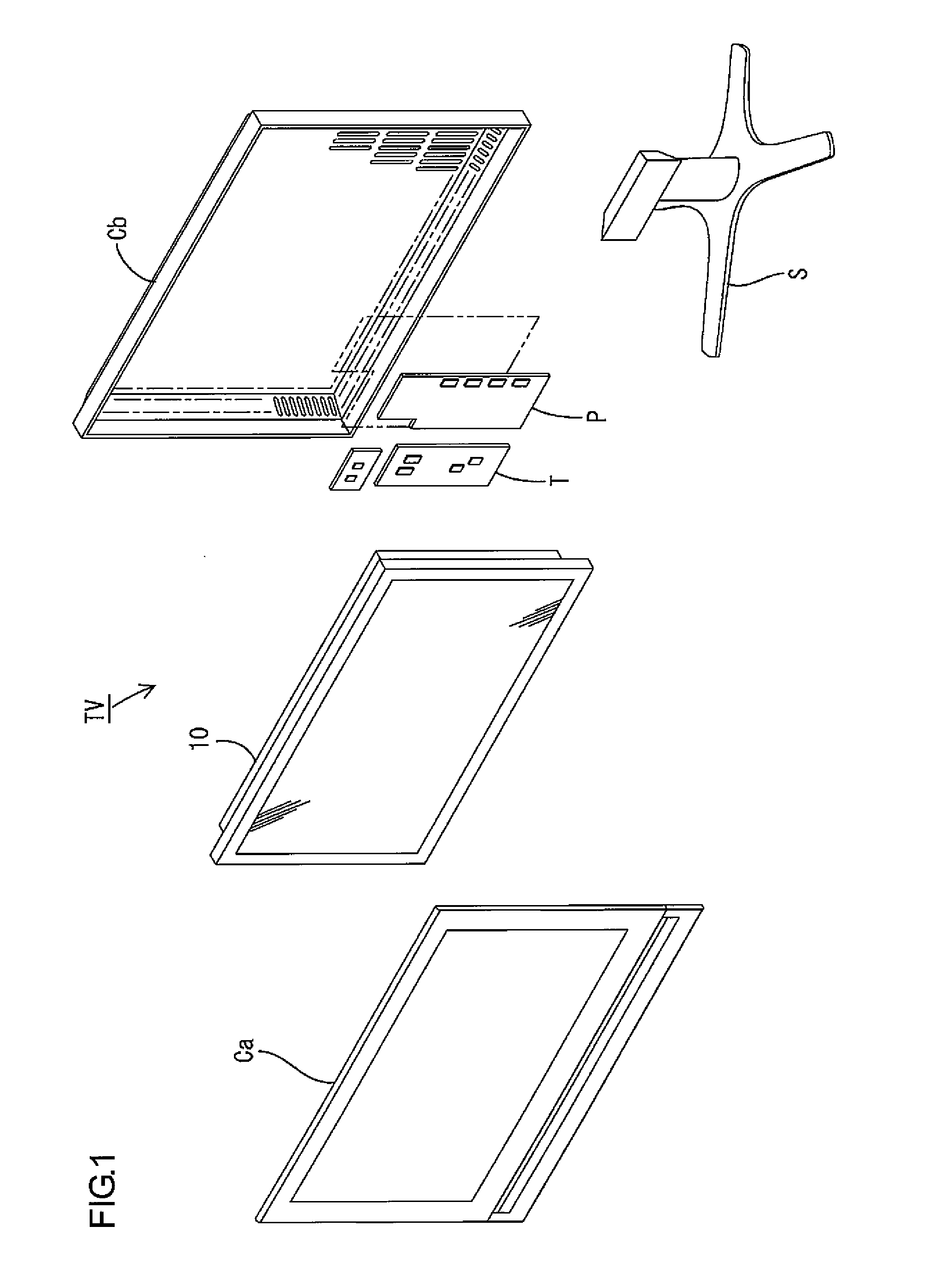
[0047]First, a construction of a television receiver TV including a liquid crystal display device 10 will be explained.
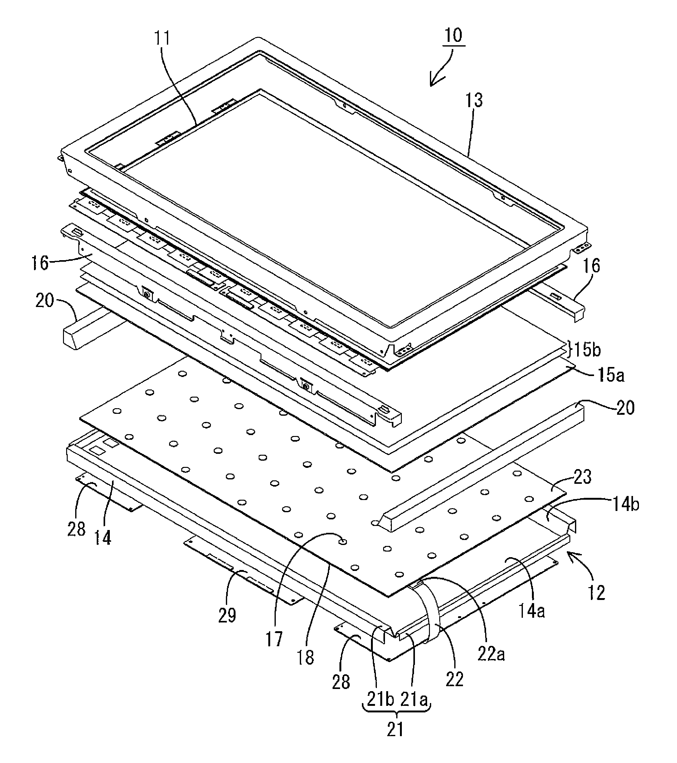
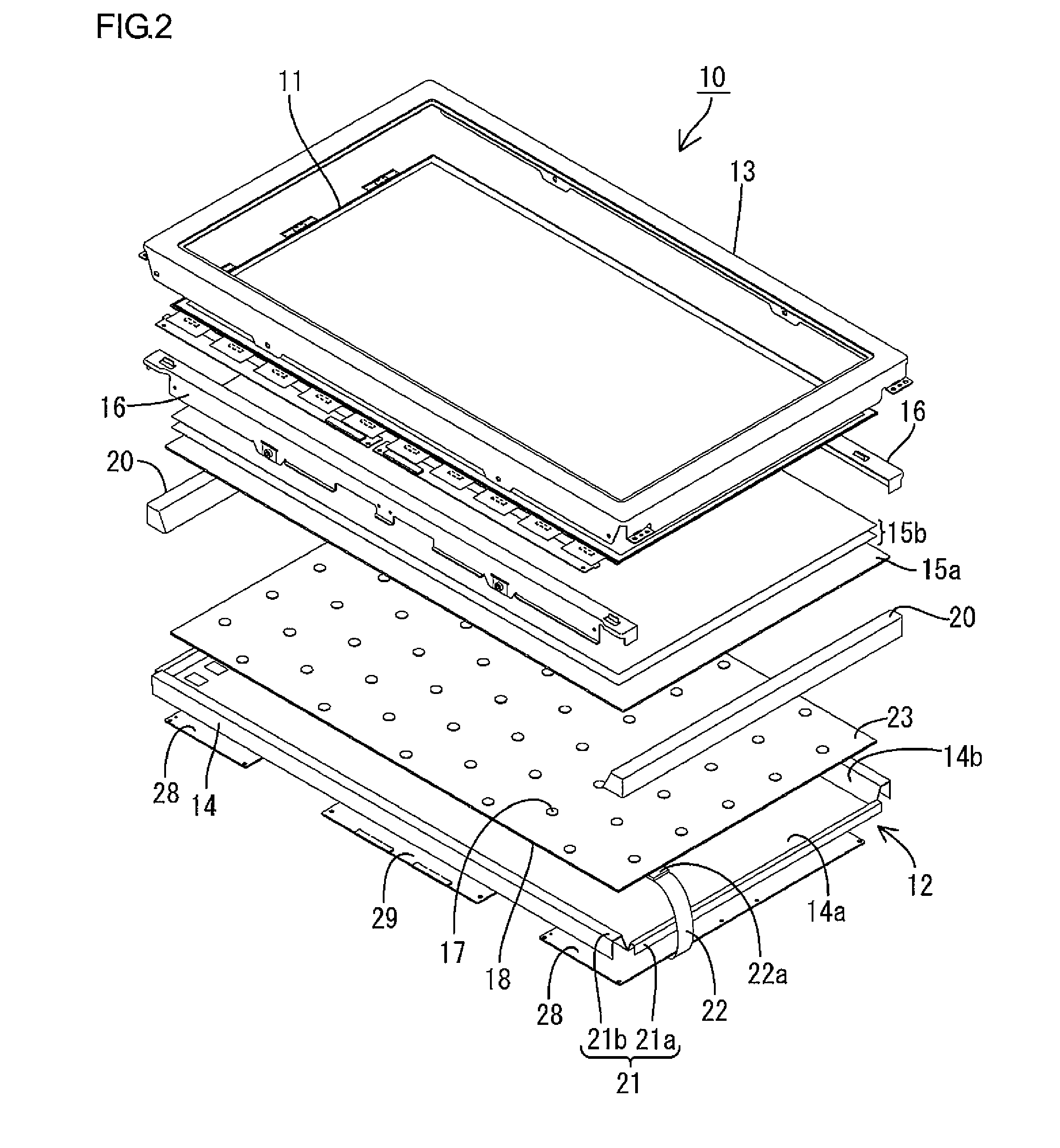
[0048]FIG. 1 is an exploded perspective view illustrating a general construction of the television receiver of this embodiment. FIG. 2 is an exploded perspective view illustrating a general construction of the liquid crystal display device included in the television receiver in FIG. 1. FIG. 3 is a cross-sectional view of the liquid crystal display device in FIG. 2. FIG. 4 is a typical view explaining a cross-sectional construction and an operation of the light guide plate of the liquid crystal display device in FIG. 2. FIG. 5 is a typical view illustrating plan arrangement of the light reflecting portions and the light scattering portions formed on the light guide plate. FIG. 6 is an explanation view illustrating an operation of the light guide plate. FIG. 7 is a gra...
second embodiment
[0108]A second embodiment of the present invention will be explained with reference to FIGS. 15 to 18. The second embodiment differs from the first embodiment in that an arrangement configuration of the LED light sources 17 (LED substrate 18) is changed, and other components and configurations are same as the above embodiment. The same parts as the above embodiment are indicated by the same symbols and will not be explained.
[0109]FIG. 15 is a cross-sectional view illustrating a cross-sectional configuration of the liquid crystal display device according to a second embodiment. FIG. 16 is a plan view illustrating a configuration of the light guide plate provided in the liquid crystal display device in FIG. 15. FIG. 17 is a plan view explaining a light reflectance distribution on the second surface of the light guide plate. FIG. 18 is a graph illustrating a light reflectance change in the light guide plate.
[0110]The LED substrate 18 that forms the light source portion of the backlight...
third embodiment
[0152]Next, a third embodiment of the present invention will be explained with reference to FIGS. 24 to 26. In the third embodiment, the arrangement of the LED light sources (LED substrate) and the configuration of the light guide plate are modified compared to the second embodiment, and other configurations are same as the second embodiment. The same parts as the second embodiment are indicated by the same symbols and will not be explained.
[0153]FIG. 24 is a plan view illustrating a cross-sectional view illustrating an arrangement configuration of the LED light sources (LED substrate) and the chassis provided in the liquid crystal display device according to the third embodiment. FIG. 25 is a plan view illustrating light reflectance distribution of the entire second surface of the light guide plate included in the liquid crystal display device in FIG. 25. FIG. 26 is a graph illustrating a light reflectance change in the short-side direction of the light guide plate in FIG. 25. In F...
PUM
 Abstract
Description
Claims
Application Information