Image forming apparatus and rear projection display apparatus

a technology of image forming apparatus and display apparatus, which is applied in the direction of lighting and heating apparatus, instruments, optical elements, etc., can solve the problems of difficult to attract observers' attention, screen disturbs sight, and image is not always displayed over the entire screen area, so as to achieve the effect of attracting observers' attention

Inactive Publication Date: 2011-08-25
SEIKO EPSON CORP
View PDF5 Cites 27 Cited by
  • Summary
  • Abstract
  • Description
  • Claims
  • Application Information

AI Technical Summary

Benefits of technology

An advantage of some aspects of the invention is to provide an image forming apparatus and a rear projection display apparatus that can effectively attract observer's interest using a substantially transparent screen.
This makes it possible to provide a rear projection display apparatus that can effectively attract observer's interest using a substantially transparent screen.

Problems solved by technology

However, in such an apparatus, problems explained below occur because the screen always has light diffusion properties.
First, when an image is not formed on the screen, the screen disturbs the sight.
Second, an image is not always displayed over the entire area of the screen.
Third, when an image is displayed on the screen widely known to the public, it is difficult to attract attention of observers.

Method used


Image

  • Image forming apparatus and rear projection display apparatus
  • Image forming apparatus and rear projection display apparatus
  • Image forming apparatus and rear projection display apparatus

Examples


first embodiment

First, an image forming apparatus according to a first embodiment of the invention is explained.

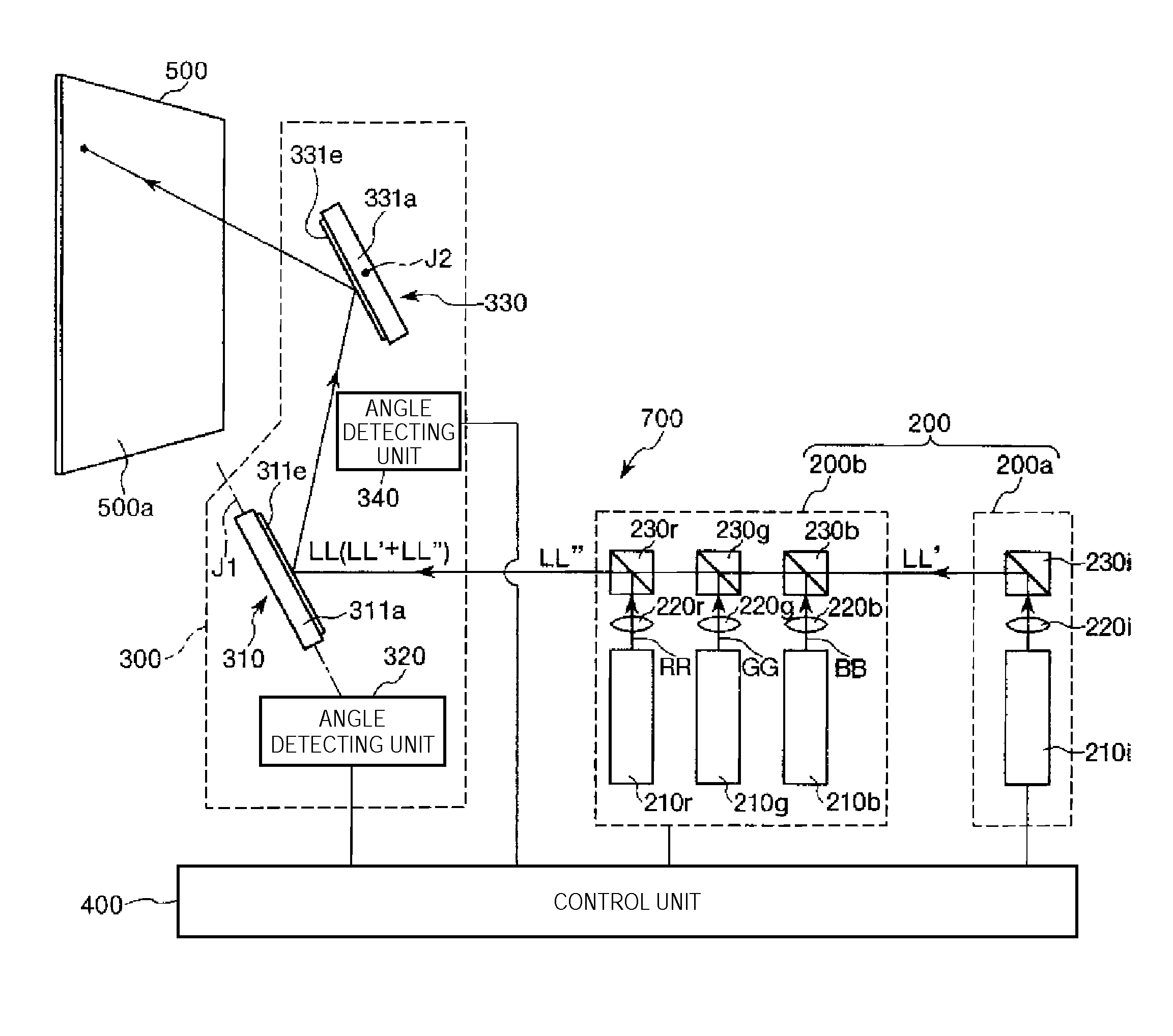
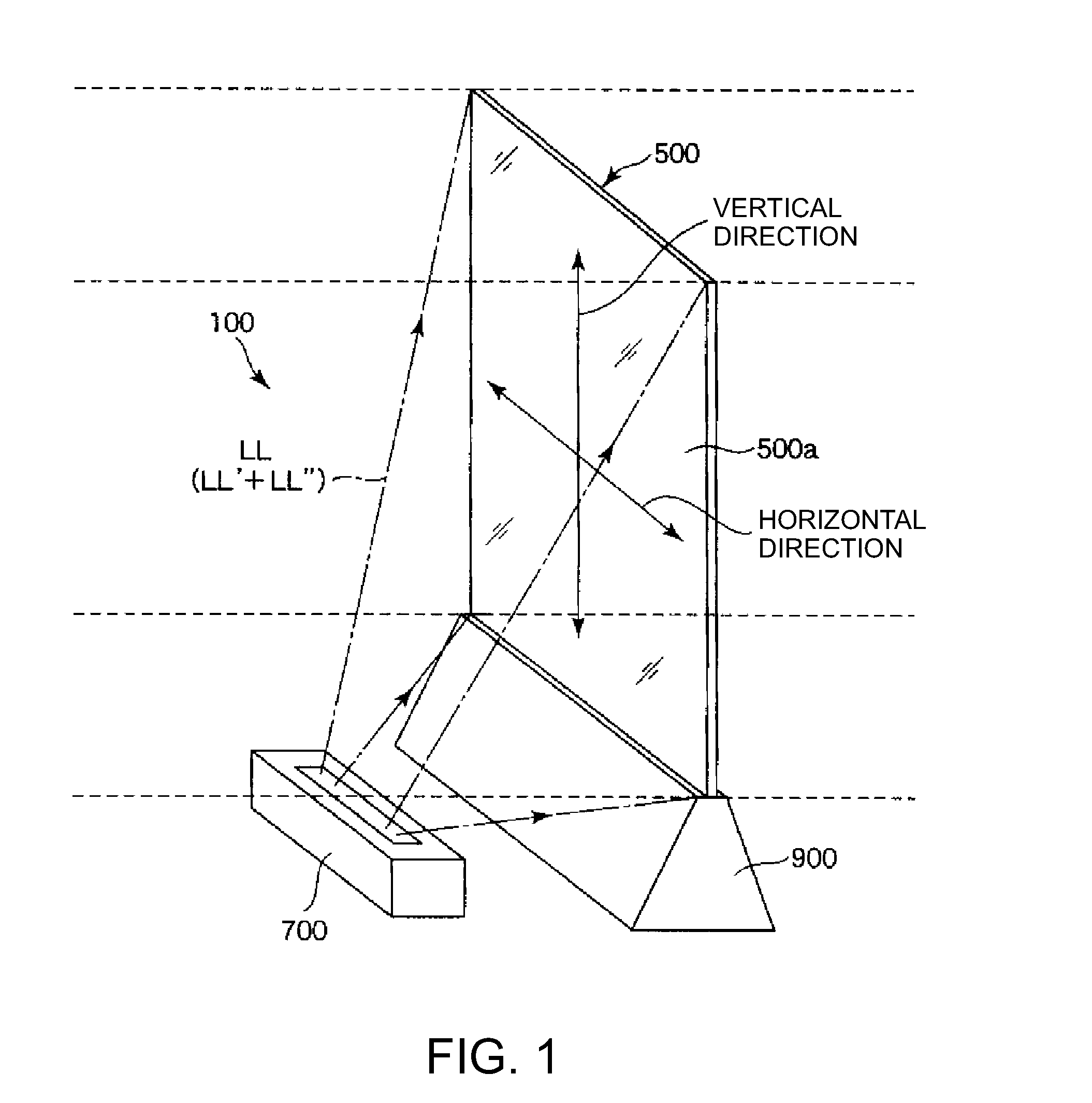
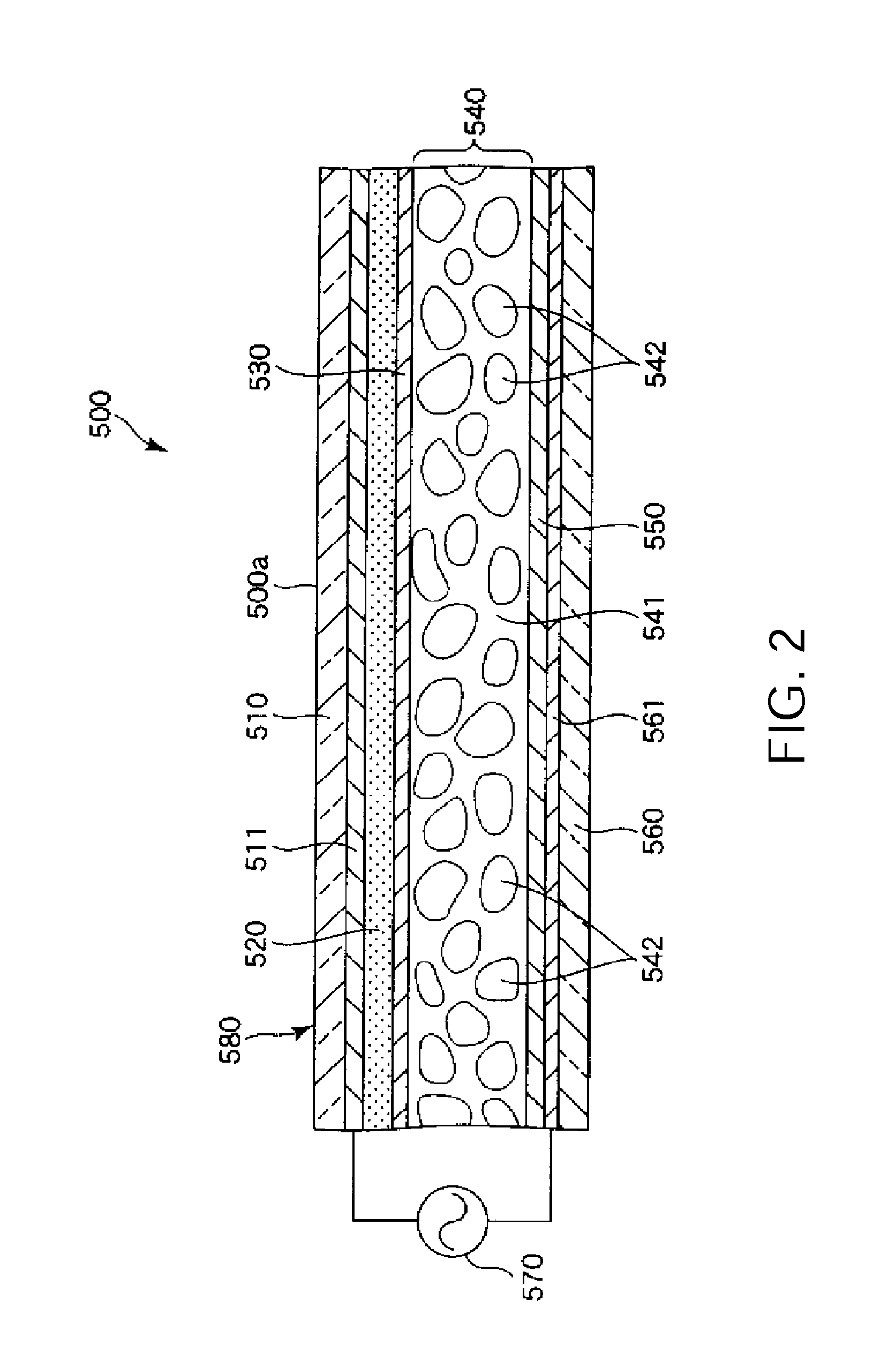
FIG. 1 is a diagram showing the image forming apparatus according to the first embodiment of the invention. FIG. 2 is a sectional view of a screen of the image forming apparatus shown in FIG. 1. FIG. 3 is a graph showing a relation between the transmittance of the screen and the intensity of voltage applied to a liquid crystal polymer composite layer. FIG. 4 is a diagram showing an equivalent circuit of the screen. FIG. 5 is a diagram showing the operation of the screen. FIG. 6 is a diagram showing a schematic configuration of a projector. FIG. 7 is a perspective view of an optical scanner of the projector. FIGS. 8A and 8B are diagrams showing the operation of the optical scanner shown in FIG. 7. FIG. 9 is a plan view showing an example of an image displayed on the screen. FIG. 10 is a plan view for explaining the driving of the projector. In the following explanation, for convenience of ...

second embodiment

An image forming apparatus according to a second embodiment of the invention is explained below.

FIG. 11 is a schematic diagram showing the configuration of a light scanning unit of the image forming apparatus according to the second embodiment of the invention.

Concerning the image forming apparatus according to the second embodiment, differences from the first embodiment are mainly explained below. Explanation of similarities is omitted.

The image forming apparatus according to the second embodiment is substantially the same as the image forming apparatus according to the first embodiment except that the configuration of the light scanning unit is different and, specifically, one optical scanner of the pair of optical scanners is replaced with a galvanometer mirror. In FIG. 11, components same as those in the first embodiment are denoted by the same reference numerals and signs.

As shown in FIG. 11, a light scanning unit 300A includes the optical scanner 310, the angle detecting unit ...

third embodiment

An image forming apparatus according to a third embodiment of the invention is explained below.

FIG. 12 is a schematic diagram showing the configuration of the image forming apparatus according to the third embodiment of the invention.

Concerning the image forming apparatus according to the third embodiment, differences from the first embodiment are mainly explained below. Explanation of similarities is omitted.

The image forming apparatus according to the third embodiment is substantially the same as the image forming apparatus according to the first embodiment except that the image forming apparatus according to the third embodiment includes a reflection mirror. In FIG. 12, components same as those in the first embodiment are denoted by the same reference numerals and signs.

As shown in FIG. 12, the image forming apparatus 100 includes the screen 500, the projector 700, and a reflection mirror 800. A relative positional relation among these components is fixed.

In such an image forming...


PUM

PropertyMeasurementUnit
refractive indexaaaaaaaaaa
transmittanceaaaaaaaaaa

Abstract

An image forming apparatus includes: a screen having a display surface; and a projector that renders an image by scanning light on the display screen, wherein the screen selects, independently in respective regions of the display surface, a light transmission state in which the light is transmitted and a light diffusion state in which the light is diffused, the screen being configured such that the region where address light is irradiated is in the light diffusion state and the region where the address light is not irradiated is in the light transmission state, and the projector scans the address light on the display surface such that an area of the display surface corresponding to an image displayed on the display surface changes to the light diffusion state.

Description

BACKGROUND1. Technical FieldThe present invention relates to an image forming apparatus and a rear projection display apparatus.2. Related ArtFor example, as an apparatus that displays a desired image (in particular, an advertisement such as CM) on a screen, there is known an apparatus configured to scan a laser beam emitted from a light source in a lateral direction and a longitudinal direction of a screen using an optical scanner and a galvanometer mirror (see, for example, JP-A-2009-134194).However, in such an apparatus, problems explained below occur because the screen always has light diffusion properties. First, when an image is not formed on the screen, the screen disturbs the sight. Second, an image is not always displayed over the entire area of the screen. In some case, an image is displayed only in a part (e.g., the center) of the screen. In such a case, a portion of the screen on which the image is not displays disturbs the sight. Third, when an image is displayed on the...

Claims


Application Information

Patent Timeline
Patent Type & Authority Applications(United States)
IPC IPC(8): G02F1/1335G02F1/01G02B26/10F21S2/00F21V14/04G02F1/13G02F1/1333G03B21/00G03B21/10G03B21/60
CPCG02B5/0236G02B5/0263G02B5/0289G02B26/085G02F1/135G02B27/104G02B27/145G02F1/133362G02F1/1334G02B26/101
Inventor MIZOGUCHI, YASUSHIKOBAYASHI, HIDEKAZUWAKABAYASHI, SHUICHIYAMAUCHI, TAISUKETAKEDA, TAKASHI
Owner SEIKO EPSON CORP
Why Eureka
Try Eureka