Reinforcement and/or anchor bolt

a technology of anchor bolts and bolts, applied in the direction of anchoring bolts, earthwork drilling and mining, mining structures, etc., can solve the problems of long curing time, high cost of chemical anchor systems, and inability to meet the needs of mining operations, and achieve the effect of inexpensive and reliable anchoring to the bedrock and little technical effor

Inactive Publication Date: 2011-08-25
HILTI AG
View PDF4 Cites 7 Cited by
  • Summary
  • Abstract
  • Description
  • Claims
  • Application Information

AI Technical Summary

Benefits of technology

[0006]It is an object of the present invention is to provide a reinforcement and / or anchor bolt, a method for reinforcing and / or anchoring bedrock in mining and / or tunnel construction, and the use of a reinforcement and / or anchor bolt in mining and / or tunnel construction, whereby the reinforcement and / or anchor bolt can be attached inexpensively and reliably to the bedrock with little technical effort.

Problems solved by technology

The drawbacks of these two different anchor systems are that chemical anchor systems are expensive and that, with so-called expansion anchors, a punctual load is applied into the bedrock.
Moreover, with chemical anchor systems, the curing is temperature-dependent, so that a long curing time has to be expected at low temperatures.
The anchors cannot be dismantled, which is especially disadvantageous when they are used in coal mining.

Method used


Image

  • Reinforcement and/or anchor bolt
  • Reinforcement and/or anchor bolt
  • Reinforcement and/or anchor bolt

Examples


first embodiment

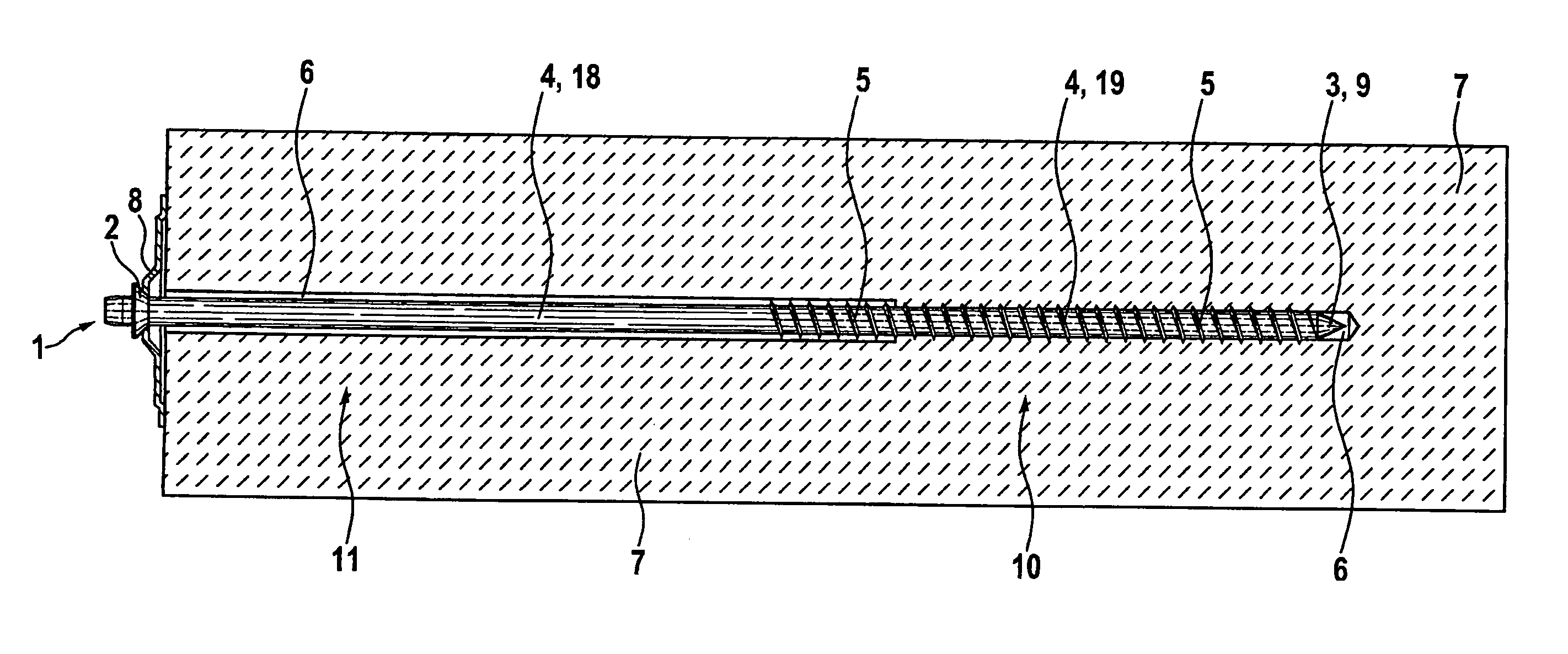
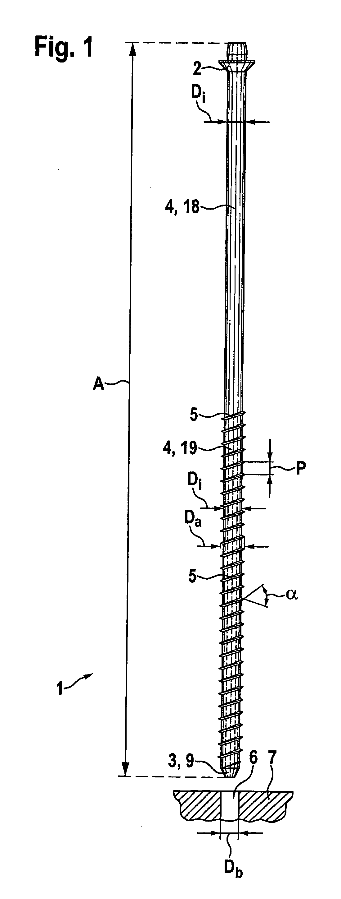
[0035]FIG. 2 shows an arrangement of the reinforcement and / or anchor bolt 1 in a bore hole 6 that has been drilled in the bedrock 7. The reinforcement and / or anchor bolt 1 is configured in the area of the bolt head 2 on the bolt shaft 18 in such a way that said bolt shaft does not have a thread 5, and in another section of the bolt shaft 4 on the bolt end 3, it has a thread 5, or else a thread 5 is formed on the bolt shaft 19. Here, the outer diameter Da of the reinforcement and / or anchor bolt 1 is 20% to 30% larger than the diameter Db of the bore hole 6. After the bore hole 6 has been drilled, for example, with a drill rod 12, whereby the bore hole 6 has a constant diameter Db, the reinforcement and / or anchor bolt 1 is screwed into the bore hole 6 in that a torque is applied to the bolt head 2. Due to the larger outer diameter Da of the reinforcement and / or anchor bolt 1 relative to the diameter Db of the bore hole 6, the thread 5 cuts its way into the bedrock 7 and a positive con...

second embodiment

[0039]FIG. 5 shows a perspective view of the drill rod 12 for drilling a bore hole 6 with a varying diameter Db as shown for the second embodiment in FIG. 3. The drill rod 12 has a drilling crown 13, a stabilizer 14, a first boring bar 15 having a small diameter, a boring tool 16 and a second boring bar 17 having a large diameter. Here, for example, the drilling crown 13, the stabilizer 14 and the first boring bar 15 have a diameter of 15 mm, the boring tool 16 has a diameter of 32 mm, and the second boring bar 17 has a diameter of 18 mm. The diameter of the boring tool 16 is thus larger than the diameter of the second boring bar 17, and the diameter of the second boring bar 17 is larger than the diameter of the first boring bar 15.

[0040]All in all, the reinforcement and / or anchor bolt 1 entails major advantages. The force that is to be exerted by the reinforcement and / or anchor bolt 1 into the bedrock 7 is applied by the thread 5 essentially positively into the bedrock 7. The reinf...


PUM


Abstract

With a reinforcement and/or anchor bolt (1) that can be used in mining and/or tunnel construction and that is to be screwed into bedrock (7), and that includes a bolt head (2), a bolt end (3), a bolt shaft (4) and a thread (5) that is at least partially configured on the bolt shaft (4), the objective is to attach the reinforcement and/or anchor bolt (1) inexpensively and reliably to the bedrock (7) with little technical effort. A ratio of the length of the reinforcement and/or anchor bolt (1) to the outer diameter of the reinforcement and/or anchor bolt (1) is greater than 20.

Description

[0001]This claims the benefit of German Patent Application DE 10 2010 002 214.4 filed Feb. 23, 2010 and hereby incorporated by reference herein.[0002]The present invention relates to a reinforcement and / or anchor bolt, to a method for reinforcing and / or anchoring bedrock in mining and / or tunnel construction, and to the use of a reinforcement and / or anchor bolt in mining and / or tunnel construction.BACKGROUND[0003]Anchor systems are used in mining and tunnel construction to prevent ground movement of the bedrock or to slow it down or to secure large spalls of the bedrock so as to allow safe operation. Here, two functional principles are known which are, at times, also combined with each other. In mechanical systems, the anchor is secured by frictional engagement, whereby mechanical rock anchors generally also have an expansion shell. In chemical systems, reinforcement rods with a curing mortar are connected to the substrate or bedrock by means of adhesion. Here, the anchors are instal...

Claims


Application Information

Patent Timeline
Patent Type & Authority Applications(United States)
IPC IPC(8): E21D21/00
CPCE21D21/0026
Inventor AYRLE, THOMAS
Owner HILTI AG
Why Eureka
Try Eureka