
Electronic device

a technology of electronic devices and printed circuit boards, applied in the direction of electrical apparatus construction details, casings/cabinets/drawers, cabinet details, etc., can solve the problems of affecting the performance of the device, etc., to achieve the effect of favorable assembly and adequate mechanical strength

Inactive Publication Date: 2003-02-11
SIEMENS AG
View PDF9 Cites 8 Cited by
  • Summary
  • Abstract
  • Description
  • Claims
  • Application Information

AI Technical Summary

Benefits of technology

is to create an electronic device of the type provided above, wherein at least one printed circuit board stands essentially perpendicular to the rear wall, wherein it is possible to achieve adequate mechanical strength, and whilst taking safety requirements into account to achieve favorably priced assembly.
The printed circuit board can be attached inexpensively and reliably to the rear wall if the bores of the holding means in the printed circuit board contain penetrating and clinch-connectable webs.
Assembly is rendered simpler if the bores of the holding means in the printed circuit board contain allocated alignment pins.
If the rear wall consists of an outer plate and an inner plate, wherein the inner plate comprises regions which are located at a distance from the outer plate from which the holding means protrude, a particular flexibility in cooling the components and also an improved cooling effect can be achieved because air circulates around both sides of the protruding regions. In this context, it is expedient if the inner plate is partially in contact with the outer plate and has regions essentially parallel to the outer plate and running at a distance from the outer plate. In this case, it is preferable with regard to cooling if at least the inner plate is made of metal.
With one simple and expedient variant of the invention, it is possible for the cooling elements to be in contact with the inner plate of the rear wall, wherein, in this case, the inner plate can be connected directly to the printed circuit board, which produces mechanical advantages in many cases, because a connection between the rear wall and the printed circuit board need not be made completely at the edge of the printed circuit board.

Problems solved by technology

In order to cool certain components, cooling fins are fitted to the printed circuit board, which leads to considerable expenditure in terms of mechanical and production technology.
However, this means that the cooling fins must be connected rigidly in a mechanical manner to the printed circuit board, otherwise the soldered joints of the power semiconductors and their connections may be damaged during the course of time and under adverse conditions.
Furthermore, the realization of the connection between the cover and the printed circuit board as a fixed connection in the manner of a screw connection or similar is a disadvantage.

Method used


Image

  • Electronic device
  • Electronic device
  • Electronic device

Examples


Embodiment Construction

)

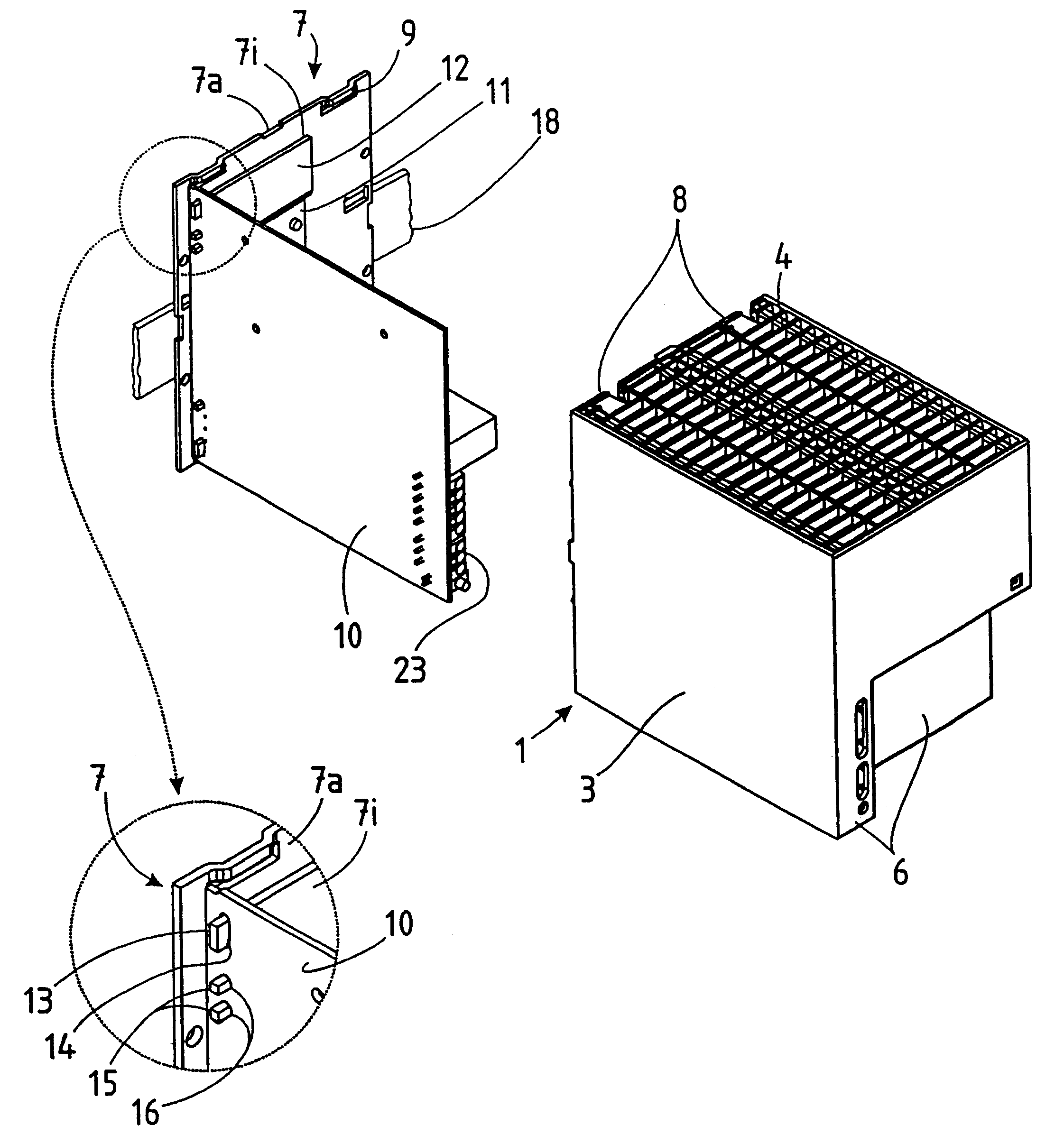
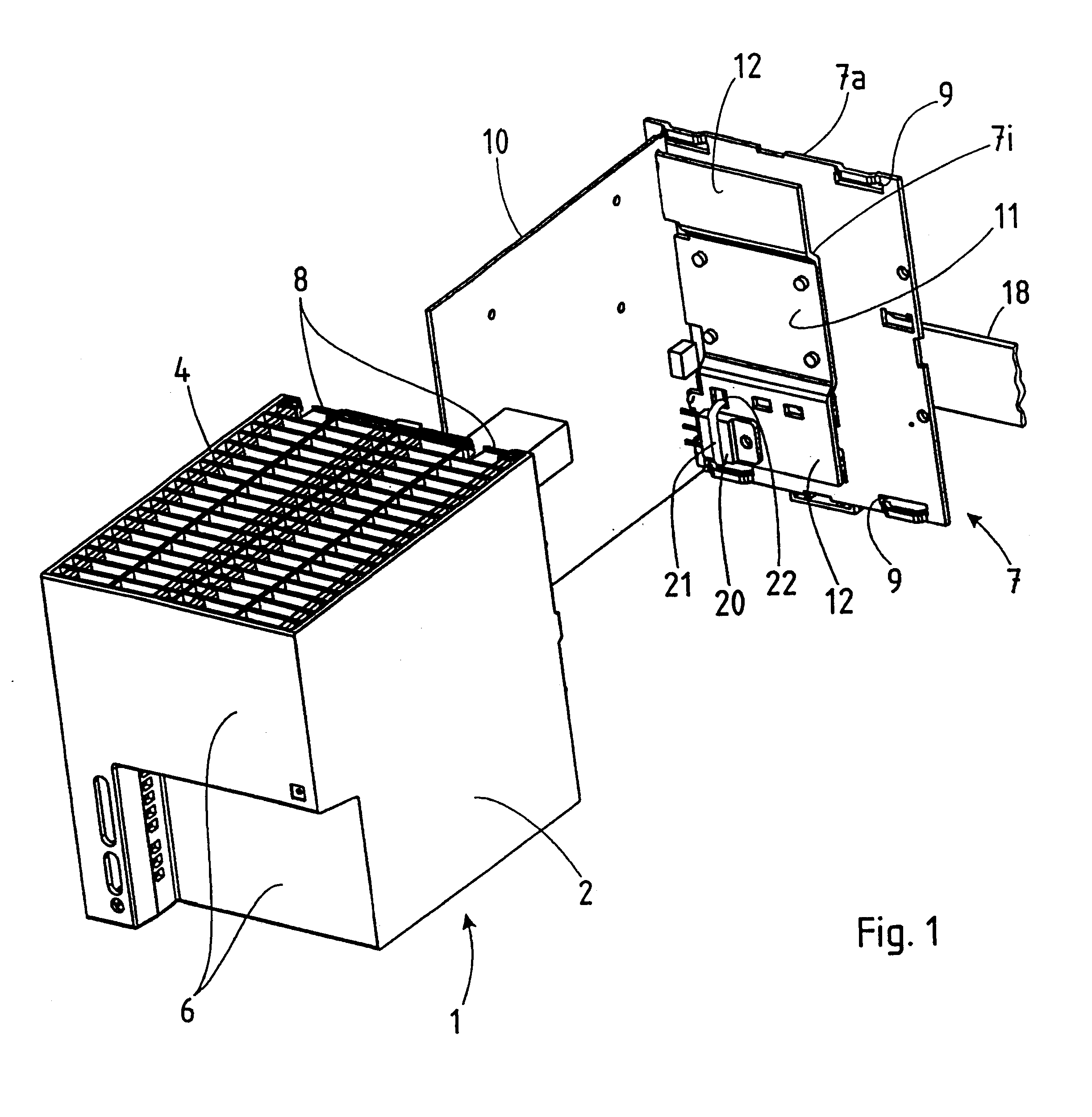
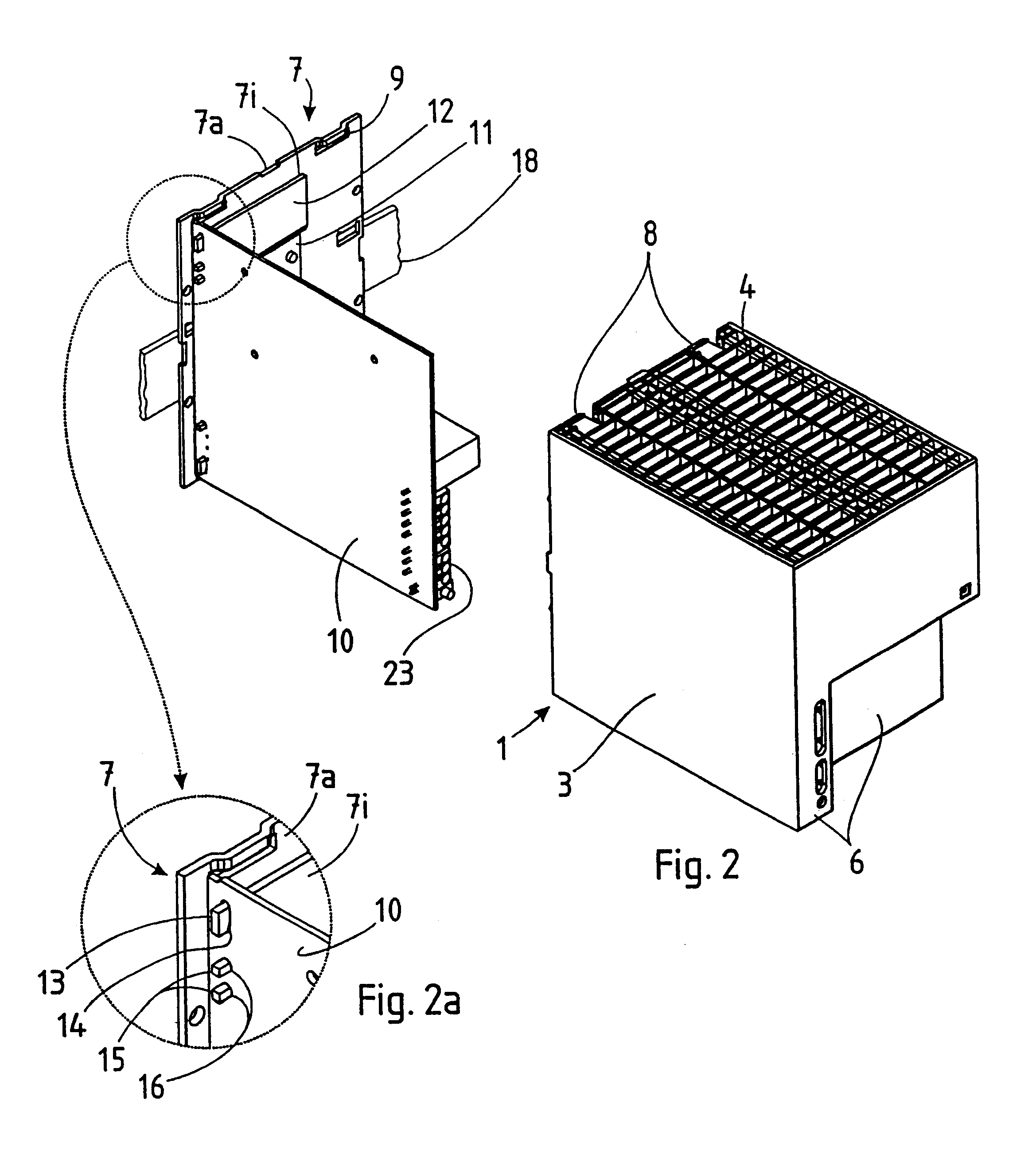
In accordance with the diagrams, a housing 1 for an electronic device comprises a right side wall 1, a left side wall 3, an upper wall 4 a lower wall 5 and a front wall 6, all of these walls being made in one piece from a synthetic material. As the diagram illustrates, the upper wall 4 and the lower wall 5 are designed with apertures in the form of a grating so that a stream of air can pass through the interior of the housing from above to below.

The housing 1 is provided with a rear wall 7 which, in the assembled condition of the device, closes off the interior of the housing to the rear. In order to connect the rear wall 7 mechanically to the housing 1, four resilient hook latches 8 protrude from the rear edges of the housing; these hook latches can penetrate apertures 9 in the rear wall 7 and can interlock with this rear wall.

The device according to the invention comprises a printed circuit board 10, which in the present case is mounted perpendicularly at the left side of the dev...


PUM


Abstract

Electronic device with a housing 1, a rear wall 7 and, accommodated in the housing, at least one printed circuit board 10 which stands essentially perpendicular to the rear wall, wherein the rear wall 7 is a part independent of the housing 1, which closes off the interior of the housing to the rear, and the printed circuit board 10 is connected in a bearing manner to the rear wall by holding means 13, 15 protruding from this and engaging with the printed circuit board.

Description

1. Field of the InventionThe invention relates to an electronic device with a housing, a rear wall and, accommodated in the housing, at least one printed circuit board which stands essentially perpendicular to the rear wall.2. Description of the Prior ArtDevices of this kind are known in many embodiments, but the requirements specified are essentially the same. In particular, the assembly of the device should be rapid and if possible should be achievable without ancillary resources; devices connected to the mains power supply should be touch-protected; and aesthetic design of the housing should be possible. Electronic devices generally also contain power semiconductors which must be cooled. The semiconductors are connected electrically to the printed circuit board and are in mechanical or thermal contact with a cooling element or a relatively large metal cooling surface.For example, a synthetic material housing is known wherein the rear wall, the two side walls and the upper and low...

Claims


Application Information

Patent Timeline
IPC IPC(8): H05K7/20H05K7/14
CPCH05K7/209H05K7/1428H05K5/03
Inventor WEINMEIER, HARALDHALBREINER, ERICH
Owner SIEMENS AG
Learn More