
Processing methods and apparatus with temperature distribution control

a technology of temperature distribution control and processing methods, applied in the direction of semiconductor/solid-state device testing/measurement, coating, chemical vapor deposition coating, etc., can solve the problems of unfavorable variations in the properties of the resulting semiconductor device, and achieve the effect of minimizing the variation in the surface temperature of the wafer

Active Publication Date: 2011-08-25
VEECO INSTR
View PDF23 Cites 21 Cited by
  • Summary
  • Abstract
  • Description
  • Claims
  • Application Information

AI Technical Summary

Benefits of technology

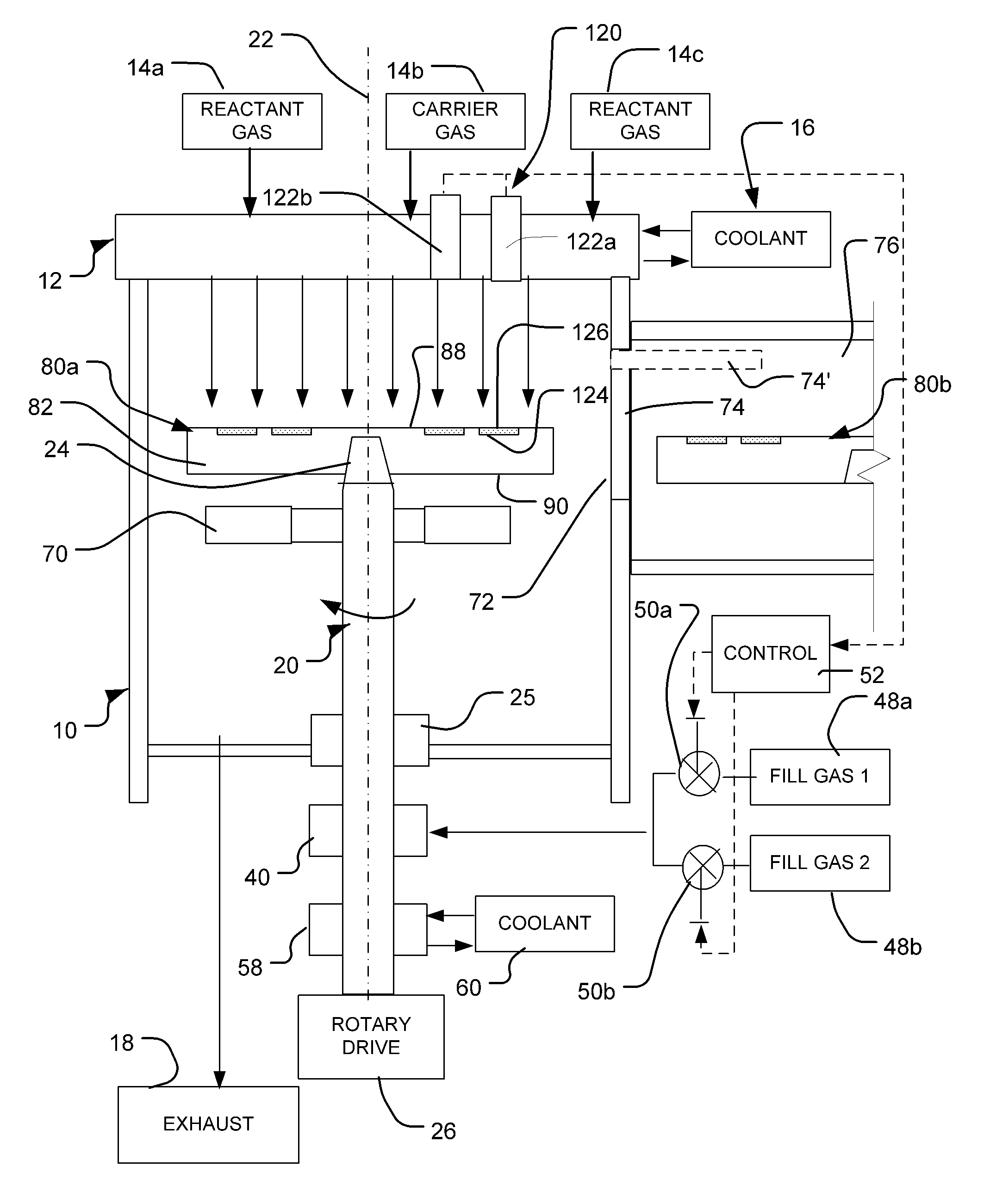
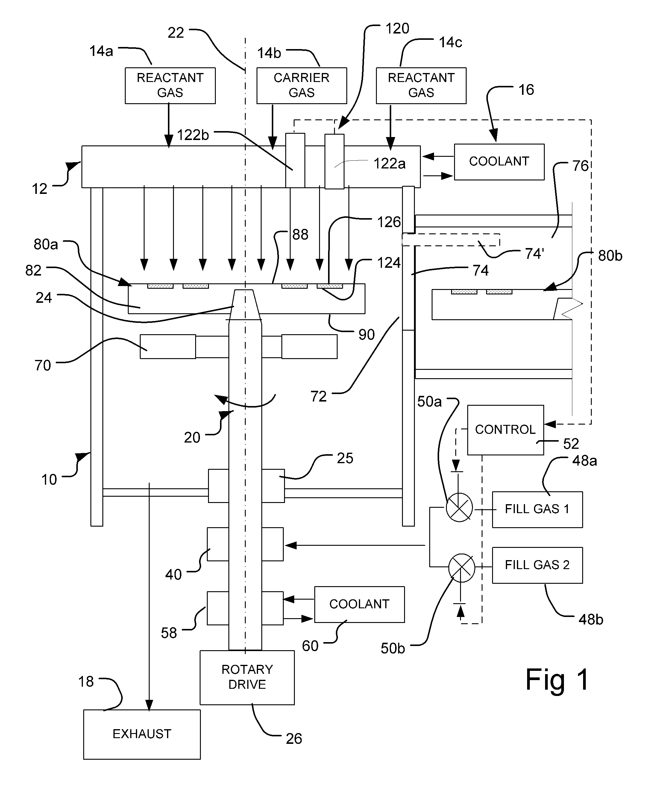
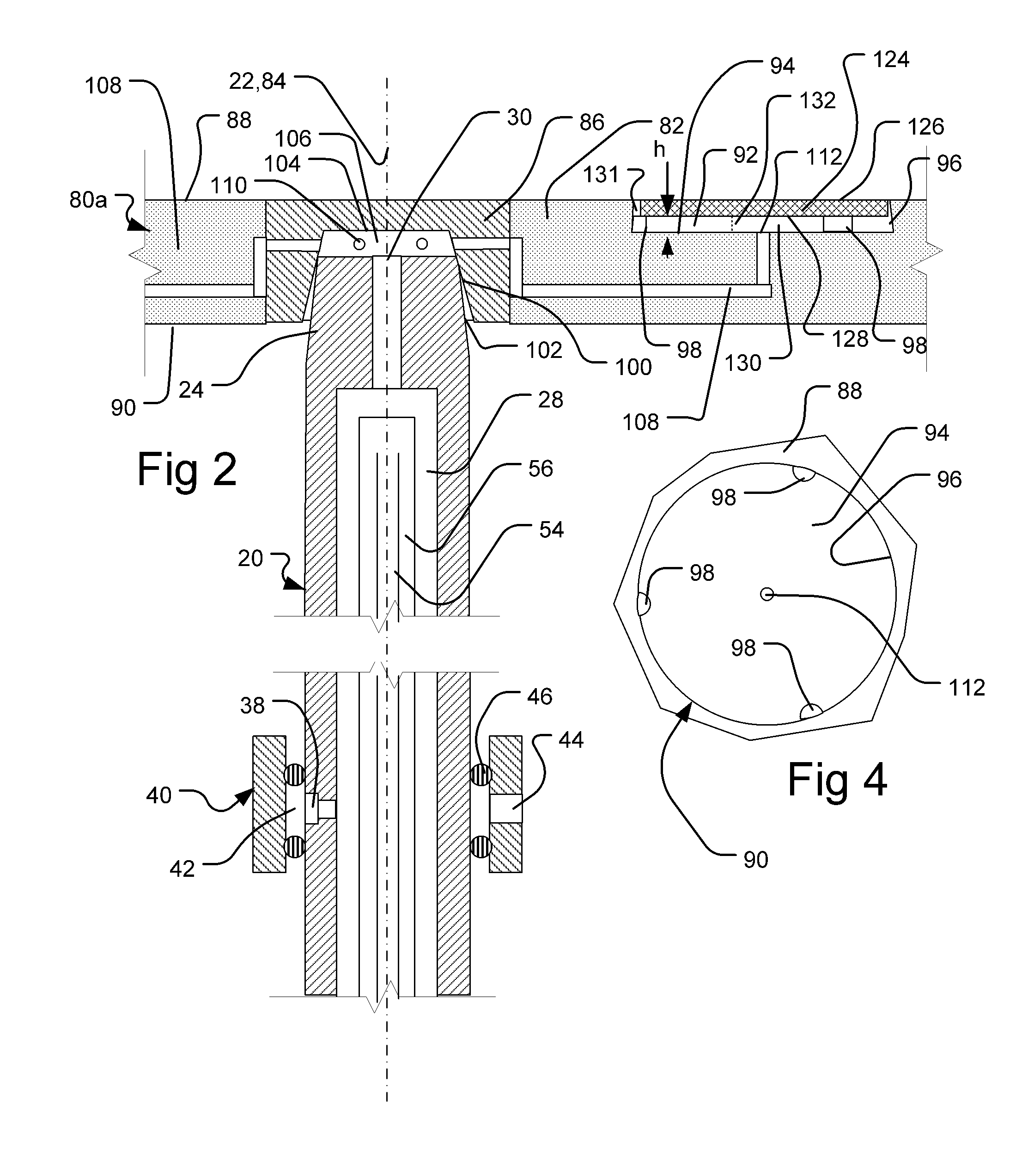
[0008]One aspect of the invention provides methods of processing wafers. A method desirably includes the step of holding one or more wafers on a carrier so that a bottom surface of each wafer directly confronts a surface of the carrier with a gap defined between the confronting surfaces and so that a top surface of each wafer is exposed. The method preferably further includes the steps of heating the wafers at least in part by heat transfer from the carrier across the gaps and, during the heating step, applying a process gas to the exposed top surfaces of the wafers. Most preferably, the method further includes the step of varying a thermal conductivity of a fill gas disposed in the gaps during the applying step. For example, the fill gas may be supplied to the gaps during the applying step and the flow rate of the supplied fill gas, the composition of the fill gas, or both, may be varied with time during the applying step. As further discussed below, the variation in the thermal conductivity of the fill gas can minimize variations in the surface temperatures of the wafers. The step of varying the conductivity of the fill gas can be performed in response to monitoring of the temperature distribution of the wafers.
[0009]In certain embodiments, the process gas tends to enter gaps between the wafers and the carrier at the periphery of the wafers. The fill gas may be supplied so as to maintain a gradient in the concentration of the fill gas in the gap beneath each wafer as, for example, a relatively high concentration of process gas and low concentration of fill gas near the periphery of the wafer and a higher concentration of fill gas near the center of the wafer. This can provide graded thermal conductivity to counteract other effects which tend to cause variation in the surface temperature across each wafer.

Problems solved by technology

Minor variations in composition of the reactive gases and in the temperature of the wafer surfaces cause undesired variations in the properties of the resulting semiconductor device.

Method used


Image

  • Processing methods and apparatus with temperature distribution control
  • Processing methods and apparatus with temperature distribution control
  • Processing methods and apparatus with temperature distribution control

Examples


Embodiment Construction

[0019]Chemical vapor deposition apparatus in accordance with one embodiment of the invention includes a reaction chamber 10 having a gas distribution element 12 arranged at one end of the chamber. The end having the gas distribution element 12 is referred to herein as the “top” end of the chamber 10. This end of the chamber typically, but not necessarily, is disposed at the top of the chamber in the normal gravitational frame of reference. Thus, the downward direction as used herein refers to the direction away from the gas distribution element 12; whereas the upward direction refers to the direction within the chamber, toward the gas distribution element 12, regardless of whether these directions are aligned with the gravitational upward and downward directions. Similarly, the “top” and “bottom” surfaces of elements are described herein with reference to the frame of reference of chamber 10 and element 12.

[0020]Gas distribution element 12 is connected to sources 14a, 14b, 14c for s...


PUM

PropertyMeasurementUnit
Electrical conductivityaaaaaaaaaa
Flow rateaaaaaaaaaa
Thermal conductivityaaaaaaaaaa

Abstract

Wafer treatment process and apparatus is provided with a wafer carrier arranged to hold wafers and to inject a fill gas into gaps between the wafers and the wafer carrier. The apparatus is arranged to vary the composition, flow rate, or both of the fill gas so as to counteract undesired patterns of temperature non-uniformity of the wafers.

Description

CROSS-REFERENCE TO RELATED APPLICATIONS[0001]This application claims the benefit of the filing date of U.S. Provisional Patent Application No. 61 / 307,497 filed Feb. 24, 2010, the disclosure of which is hereby incorporated herein by reference.BACKGROUND OF THE INVENTION[0002]The present invention relates to wafer processing apparatus, to wafer carriers for use in such processing apparatus, and to methods of wafer processing.[0003]Many semiconductor devices are formed by processes performed on a substrate. The substrate typically is slab of a crystalline material, commonly referred to as a “wafer.” Typically, the wafer is formed from a crystalline material, and is in the form of a disc. One common process is epitaxial growth. For example, devices formed from compound semiconductors such as III-V semiconductors typically are formed by growing successive layers of the compound semiconductor using metal organic chemical vapor deposition or “MOCVD.” In this process, the wafers are exposed...

Claims


Application Information

Patent Timeline
IPC IPC(8): C23C16/455C23C16/458C23C16/52
CPCC23C16/45521C23C16/4584H01L21/68792H01L21/67109H01L21/68785C23C16/52H01L21/67248H01L22/26H01L21/0254H01L21/0262
Inventor GURARY, ALEXBELOUSOV, MIKHAILBOGUSLAVSKIY, VADIMMITROVIC, BOJAN
Owner VEECO INSTR
Learn More