Power source apparatus with electrical components disposed in the battery blocks

a power source and battery block technology, applied in the direction of cell components, electric devices, secondary cells servicing/maintenance, etc., can solve the problems of over-sized outer cases and over-sized electrical components, and achieve the effect of avoiding enlargement of outer cases

Inactive Publication Date: 2011-08-25
SANYO ELECTRIC CO LTD
View PDF13 Cites 160 Cited by
  • Summary
  • Abstract
  • Description
  • Claims
  • Application Information

AI Technical Summary

Benefits of technology

[0008]To achieve the object described above, the power source apparatus for the first aspect of the present invention can be provided with battery blocks made up of a plurality of battery cells connected in battery stacks, and an outer case that holds the battery blocks. A block circuit board to control the battery cells that make up each bat...

Problems solved by technology

Consequently, the number of components housed in the electrical component case increases making th...

Method used


Image

  • Power source apparatus with electrical components disposed in the battery blocks
  • Power source apparatus with electrical components disposed in the battery blocks
  • Power source apparatus with electrical components disposed in the battery blocks

Examples


first embodiment

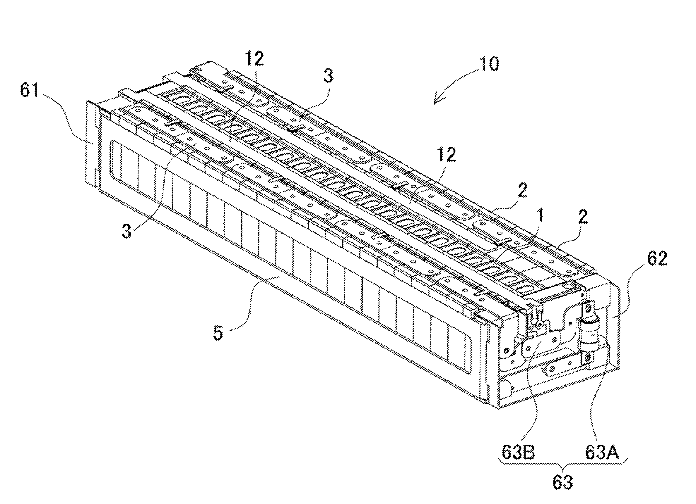
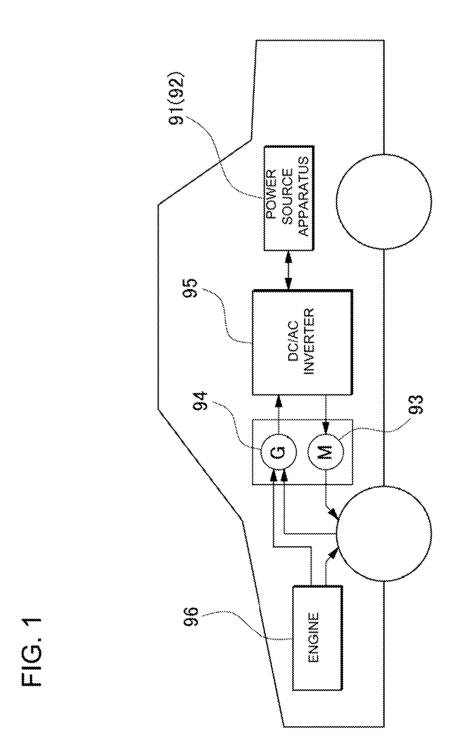
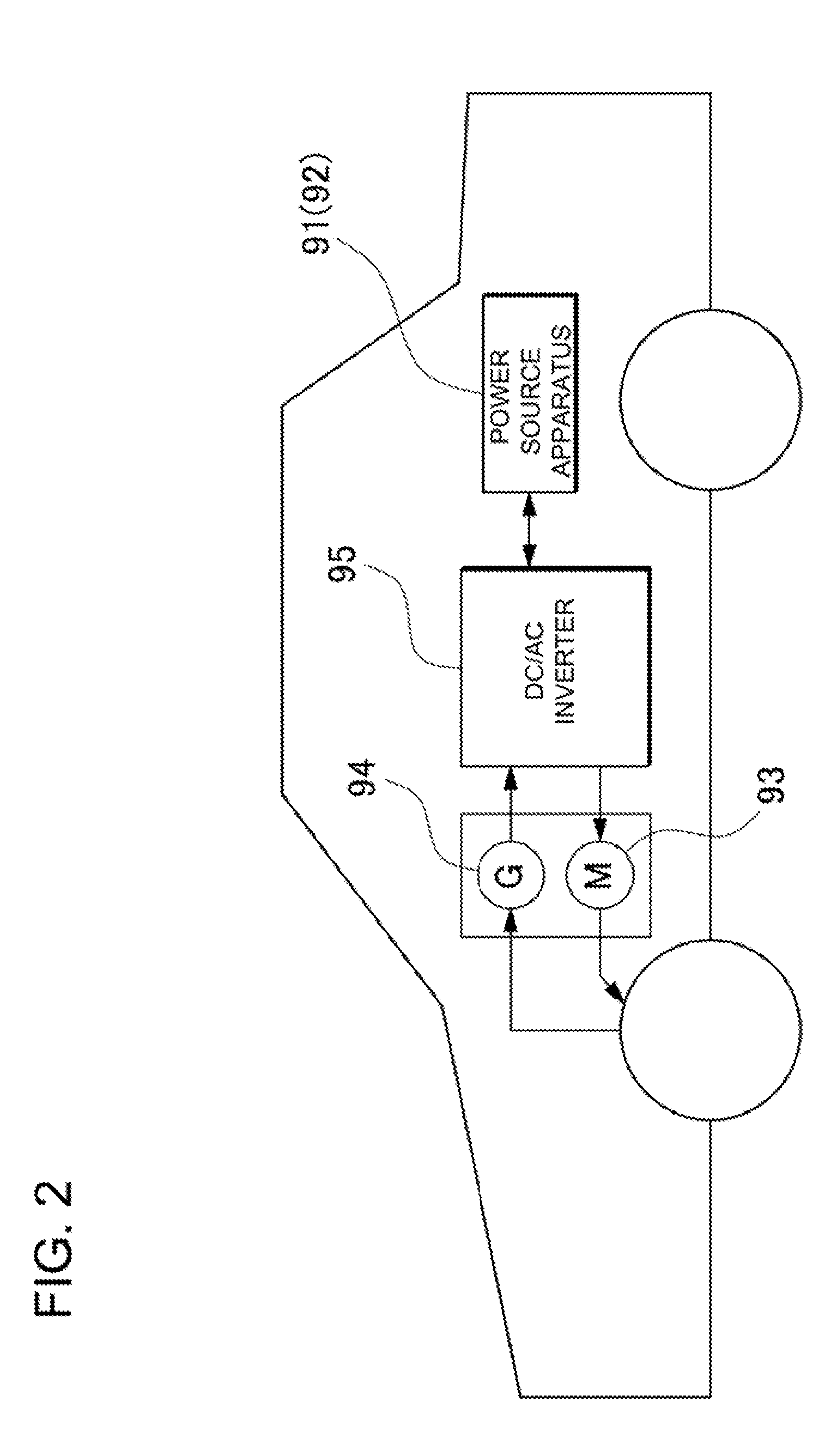
[0048]The power source apparatus 91 for the first embodiment is carried on-board the vehicles described above and is shown in detail in FIGS. 3-20. Here, FIG. 3 is an oblique view of the power source apparatus 91, FIG. 4 is an oblique view showing the cover plate removed from the outer case 70 in FIG. 3, FIG. 5 is an oblique view of one of the battery block cases 75 in FIG. 4, FIG. 6 is an exploded oblique view of the battery block case 75 in FIG. 5, FIG. 7 is an oblique view of the battery block 50 in FIG. 6, FIG. 8 is an oblique view of the battery block 50 in FIG. 6 viewed from the backside, FIG. 9 is an exploded oblique view of the battery block 50 in FIG. 7, FIG. 10 is an exploded oblique view of the first endplate 4A region of the battery stack in FIG. 7, FIG. 11 is an exploded oblique view of the second endplate 4B region of the battery stack in FIG. 8, FIG. 12 is an exploded oblique view of the electrical component holder 62 in FIG. 11, FIG. 13 is a block diagram showing the...

second embodiment

[0084]As shown in FIGS. 21-25, the power source apparatus 92 for the second embodiment is provided with battery stacks 10B having a plurality of rectangular battery cells 1 stacked with cooling gaps 53, forced ventilating equipment 59 to force ventilation through the battery stack 10B cooling gaps 53, and an outer case 70B to hold the battery stacks 10B. The outer case 70B is made up of an upper case 72B and a lower case 71B, and flanges 74B are provided on the upper and lower cases.

[0085]A battery stack 10B has separators 52 intervening between the stacked battery cells 1. The separators 52 are made in a shape that forms cooling gaps 53 between the battery cells 1. The separators 52 of FIGS. 25 and 26 have a structure that fits together with, and joins battery cells 1 on both sides. Adjacent battery cells 1 can be stacked in a manner preventing position shift via separators 52 that fit together with the battery cells 1.

[0086]Separators 52 are made of insulating material such as pla...

third embodiment

[0102]Although rectangular batteries having box-shaped or flat-plate-shaped external cases were used as the battery cells 1 in the examples above, the power source apparatus is not limited to that configuration and circular cylindrical battery cells can also be used. As a third embodiment, FIG. 27 shows an example of a battery block using circular cylindrical battery cells 1B. As shown in this figure, circular cylindrical batteries are connected in an upright standing orientation to form a battery stack 10C that is disposed on top of a cooling plate 7C. A block circuit board 60B is disposed at one end of the battery stack 10C, and an electrical component holder 62B that holds electrical components 63C is disposed at the other end. In this structure as well, there is no need for a special-purpose electrical component case and electrical components for controlling the battery block are disposed in each battery block. Consequently, this structure has the positive feature that the overa...


PUM


Abstract

The power source apparatus is provided with battery blocks 50 made up of a plurality of battery cells 1 connected in battery stacks, and an outer case that holds the battery blocks 50. A block circuit board 60 to control the battery cells 1 that make up each battery stack and electrical components 63 connected to the block circuit board 60 or the battery stack are disposed in the end-planes of each battery stack. With this arrangement, electrical components are disposed in each battery block eliminating the need for a special purpose electrical component case and allowing outer case enlargement to be avoided.

Description

BACKGROUND OF THE INVENTION[0001]1. Field of the Invention[0002]The present invention relates to a high-current power source apparatus primarily used as the power source for a motor that drives an automobile such as a hybrid car or electric vehicle.[0003]2. Description of the Related Art[0004]A vehicle, such as an electric vehicle that is driven by an electric motor or a hybrid car that is driven by both a motor and an engine, carries on-board a power source apparatus with battery cells housed in an outer case. To deliver motor output that can drive the vehicle, the power source apparatus has many battery cells connected in series as battery blocks that have high output voltage. By housing the battery blocks inside an outer case, the battery cells can be protected from external impact forces, and dust, dirt, and moisture prevention can be designed-in. To properly control the battery cells, a micro-controller board with various control circuits is needed to detect and monitor paramet...

Claims


Application Information

Patent Timeline
IPC IPC(8): H01M10/42B60K6/28B60L3/00B60L11/18H01M10/48H01M10/60H01M10/613H01M10/617H01M10/625H01M10/643H01M10/647H01M10/651H01M10/652H01M10/653H01M10/6554H01M10/6556H01M10/6557H01M10/6563H01M10/6566H01M10/6569H01M10/658H01M10/663H01M50/209H01M50/213H01M50/264H01M50/284H01M50/289H01M50/505H01M50/51H01M50/512H01M50/569
CPCH01M2/0473Y02T10/7011H01M2/206H01M10/0525H01M10/425H01M10/482H01M10/5004H01M10/5008H01M10/5016H01M10/5032H01M10/5038H01M10/504H01M10/5053H01M10/5057H01M10/5067H01M10/5073H01M10/5077H01M2/1077H01M10/625H01M10/653H01M10/6563H01M10/647H01M10/6556H01M10/6568H01M10/652H01M10/6554H01M10/617H01M10/6566H01M10/613Y02E60/10H01M50/15H01M50/51H01M50/505H01M50/209H01M50/284H01M50/213H01M50/289H01M50/512H01M50/264H01M50/569
Inventor ASAI, YASUHIRONISHIHARA, YOSHIMOTOOHKURA, KAZUMIMIYAZAKI, YUTAKA
Owner SANYO ELECTRIC CO LTD
Why Eureka
Try Eureka