Transmitter with a relative-time timer

a technology of relative timer and data transmitter, which is applied in the field of data transmitters, can solve the problems of power supply, data may not be examined, and significant gaps in time before the data transmitted to the control system is examined

Active Publication Date: 2011-08-25
MICRO MOTION INC
View PDF12 Cites 5 Cited by
  • Summary
  • Abstract
  • Description
  • Claims
  • Application Information

AI Technical Summary

Problems solved by technology

There may be significant gaps in time before the data transmitted to the control system is examined.
In some situations, the data may not be examined unless there is a detected problem in the flow.
One problem with the use of a real-time clock is that in order to maintain an accurate time, the clock must be provided with power even during times when the transmitter is not being used, i.e., the transmitter is not powered.
Therefore, prior art transmitters having real-time clocks have required a b...

Method used


Image

  • Transmitter with a relative-time timer
  • Transmitter with a relative-time timer
  • Transmitter with a relative-time timer

Examples


Embodiment Construction

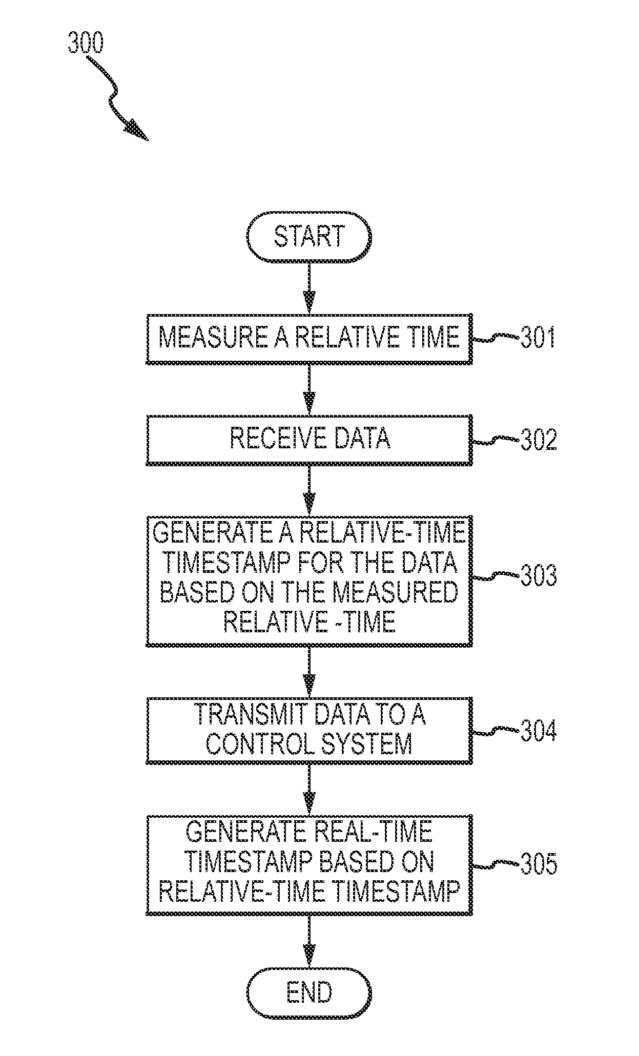
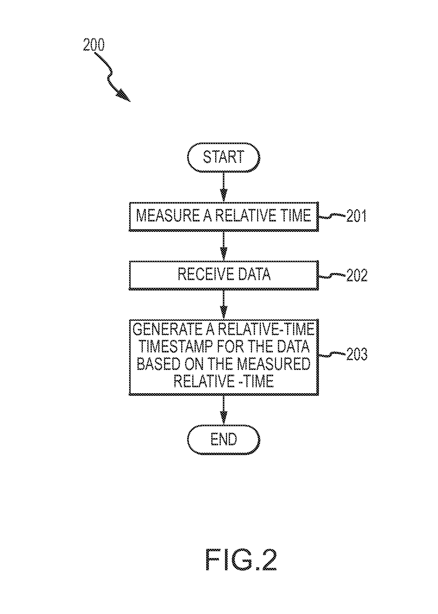
[0053]FIGS. 1-3 and the following description depict specific examples to teach those skilled in the art how to make and use the best mode of the invention. For the purpose of teaching inventive principles, some conventional aspects have been simplified or omitted. Those skilled in the art will appreciate variations from these examples that fall within the scope of the invention. Those skilled in the art will appreciate that the features described below can be combined in various ways to form multiple variations of the invention. As a result, the invention is not limited to the specific examples described below, but only by the claims and their equivalents.

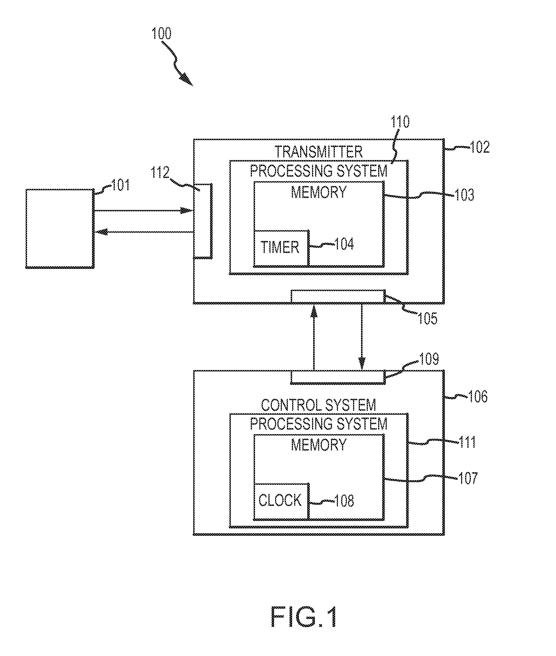
[0054]FIG. 1 shows a data processing system 100 according to an embodiment of the invention. The data processing system 100 according to the embodiment shown in FIG. 1 includes a measuring device 101, a transmitter 102, and a control system 106. It should be understood that while the discussion below is directed to a flow meter 10...


PUM


Abstract

A transmitter (102) is provided. The transmitter (102) comprises a first communication interface (112) for receiving data. The transmitter (102) also comprises a timer (104) for measuring a relative-time and a processing system (110) for providing the data with a relative-time timestamp. A second communication interface (105) is provided for outputting the relative-time timestamped data.

Description

TECHNICAL FIELD[0001]The present invention relates to data transmitters, and more particularly, to data transmitters having a relative-time timer for generating relative-time timestamps for transmitted data.BACKGROUND OF THE INVENTION[0002]Transmitters are used in a variety of industries and their uses differ widely. However, one particular implementation is a transmitter in communication with a measuring instrument, such as a fluid flow meter. Typically, the fluid flow meter is connected inline in a pipeline or the like and therefore is generally located remote from a central control station or other processing system. The transmitter may receive signals from the flow meter and transmit the signals to a control system or the like for further processing.[0003]In certain situations, a vast amount of information may be transmitted to the control system without a user / operator actually examining the information. There may be significant gaps in time before the data transmitted to the c...

Claims


Application Information

Patent Timeline
IPC IPC(8): H04W24/00
CPCG05B19/408H04Q9/04G05B2219/34413G05B2219/31126G05B23/02H04Q9/00G04F1/005G04G5/00G05D7/06G08C17/02H04B1/02
Inventor HAYS, PAUL J
Owner MICRO MOTION INC
Why Eureka
Try Eureka