Force multiplying motorcycle retaining strap

Inactive Publication Date: 2011-09-01
MILLER ROBERT W
View PDF15 Cites 16 Cited by
  • Summary
  • Abstract
  • Description
  • Claims
  • Application Information

AI Technical Summary

Benefits of technology

[0018]It will be appreciated that in the normal course only one cam buckle assembly is needed to effectively perform any restraining or release. The complementing second piece that forms the other part of the pulley asse

Problems solved by technology

These restraints often require very large tension levels, particularly when robust suspension elements need to be controlled.
Thus while suitable for the purposes intended, the need for a wind-up mechanism and a lever dimension necessary to produce the desired level of force limits the usefulness thereof in the cra

Method used


Image

  • Force multiplying motorcycle retaining strap
  • Force multiplying motorcycle retaining strap
  • Force multiplying motorcycle retaining strap

Examples


Example

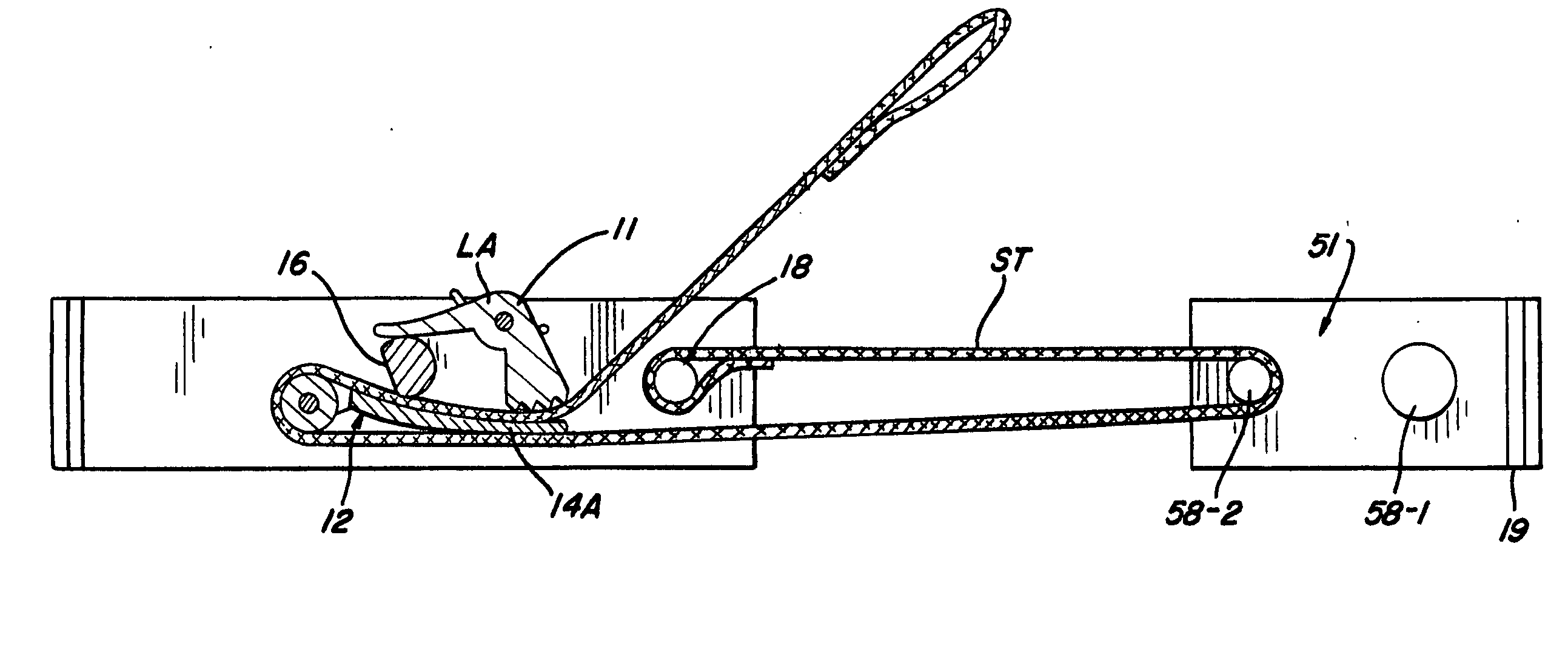
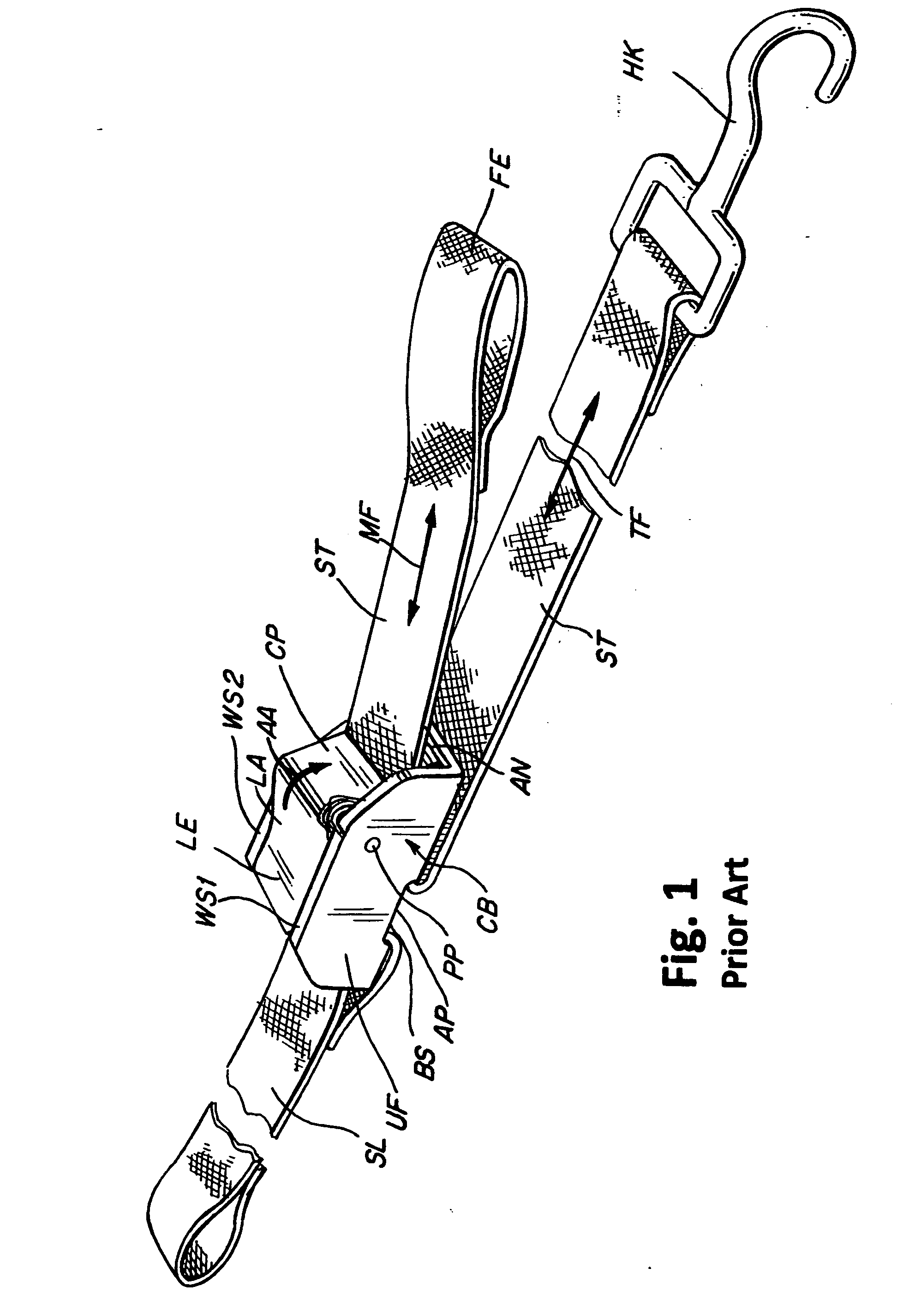
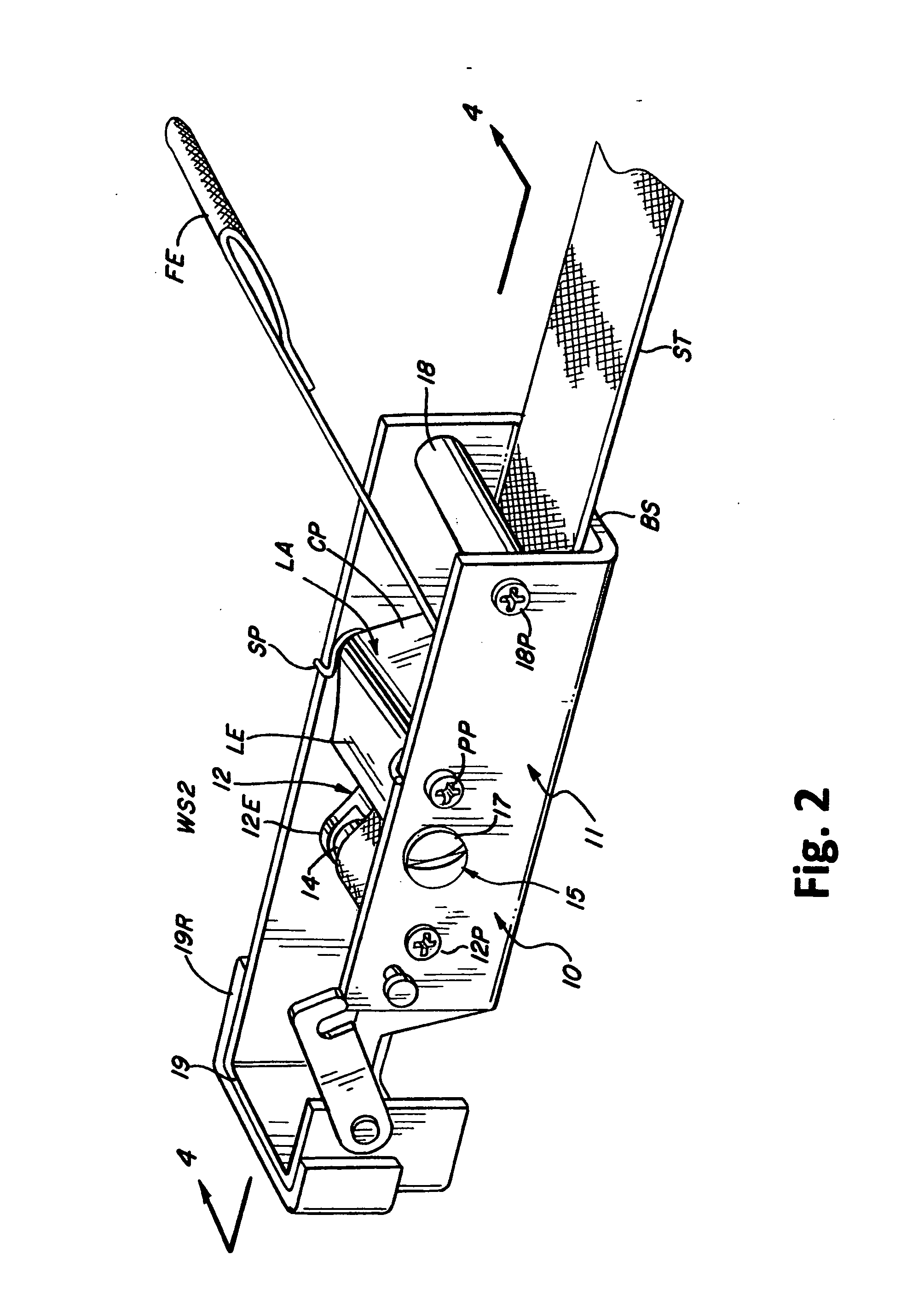
[0025]As shown in FIG. 1 a conventional cam buckle assembly generally designated CB comprises a single piece unitary frame UF of a generally C-shaped section defined by a bottom surface BS spanning between two lateral walls WS1 and WS2. A transverse pivot pin PP extends between the walls WS1 and WS2 proximate the one ends thereof to support an L-shaped lever assembly LA at the junction of a lever LE and a generally orthogonal cam piece CP.

[0026]A helical bias spring SP on pin PP is compressed between wall WS1 and the lever LE to urge the free end of the cam piece CP in the direction of arrow AA towards an anvil piece AN supported on the bottom surface BS, capturing a load carrying strap ST therebetween as it is passed through an aperture AP in the bottom surface BS against the tension force TF carried by the strap to an end hook HK corresponding to the manually applied tensioning force at the strap's free end FE. A strap loop SL around the other portion of the bottom surface BS bord...


PUM


Abstract

A generally U-sectioned cam buckle frame is modified to include a first turning roller aligned transversely across the frame proximate the free end of a release lever. A generally planar tongue having one end pivoted adjacent the first roller extends within the frame under the cam piece connected to the release lever provides a force transfer structure for a strap is inserted between the tongue and the frame bottom surface, around the first roller to pass between the cam piece and the other side of the tongue. Other transverse rollers may be included in the frame to form a pulley arrangement and one end of a frame side wall may be convolved to form a hook assembly.

Description

REFERENCE TO RELATED APPLICATIONS[0001]This application obtains the benefit of the earlier filing date of U.S. Provisional Application Ser. No. 61 / 338,993 filed on Mar. 1, 2010.BACKGROUND OF THE INVENTION[0002]1. Field of the Invention[0003]The present invention relates to motorcycle transport restraints, and more particularly to restraining strap clasping mechanisms combined with pulley pivots for increasing the force levels obtained from the combination.[0004]2. Description of the Prior Art[0005]The outdoor recreation customs and habits that have developed here in the United States adapted to the grandiose and large landscapes of the country, with a consequent reliance on all sorts of motorized vehicles that either bring us closer to nature, as for example the motorcycle, or are specialized for off-road and / or all terrain use. At the same time the grand dimensions of the country and its economic stability have also evolved a well developed highway system which then has even furthe...

Claims


Application Information

Patent Timeline
IPC IPC(8): A44B11/02
CPCB60P3/079Y10T24/2175B60P7/083
Inventor MILLER, ROBERT W.
Owner MILLER ROBERT W
Why Eureka
Try Eureka