
Optical tomography measurement device

a tomography and optical technology, applied in the field of optical tomography measurement devices, can solve the problems of high processing load, reduced reliability of reconstruction precision, complicated measurement configuration in such cases, etc., and achieve the effect of reducing processing load, preventing or suppressing the reduction of processing load

Inactive Publication Date: 2011-09-01
FUJIFILM CORP
View PDF4 Cites 2 Cited by
  • Summary
  • Abstract
  • Description
  • Claims
  • Application Information

AI Technical Summary

Benefits of technology

[0013]In consideration of the above circumstances, an object of the present invention is to provide an optical tomography measurement device that can prevent or suppress a reduction in image reconstruction precision accompanying a reduction in the computation load.
[0016]When this is being performed, since reference data is influenced by fluorescent light components generated by the fluorescent marking agent outside of the measurement plane, a reduction in image reconstruct precision can be prevented or suppressed by correcting the reference data based on the first data and second data for illumination positions positioned on either side of the measurement plane, respectively, so as to remove these extraneous fluorescent light components from the reference data.
[0018]According to this aspect of the present invention, the change component changes the illumination position to the first illumination position and the second illumination position symmetrically disposed on either side of the measurement plane. The device configuration of the present invention can thereby be simplified further.
[0020]According to this aspect of the present invention, the illumination component has three light sources, the reference light source that illuminates the excitation light onto the reference position, the first light source that illuminates the excitation light onto the first illumination position, and the second light source that illuminates the excitation light onto the second illumination position. Consequently illumination position can be readily changed.
[0029]According to the present exemplary embodiment as explained above, an effect can be exhibited in which a reduction in image reconstruct precision accompanying a reduction in the processing load can be prevented or suppressed.

Problems solved by technology

While such reconstruction of tomographic images is performable by computation in a 3-dimensional model, configuration for measurement in such cases is complicated and there is a high processing load.
However, since light within the living organism scatters 3-dimensionally, a problem arises in that the reliability of reconstruction precision reduces due to cross-talk with fluorescent body distribution in adjacent cross-sections.

Method used


Image

  • Optical tomography measurement device
  • Optical tomography measurement device
  • Optical tomography measurement device

Examples


first exemplary embodiment

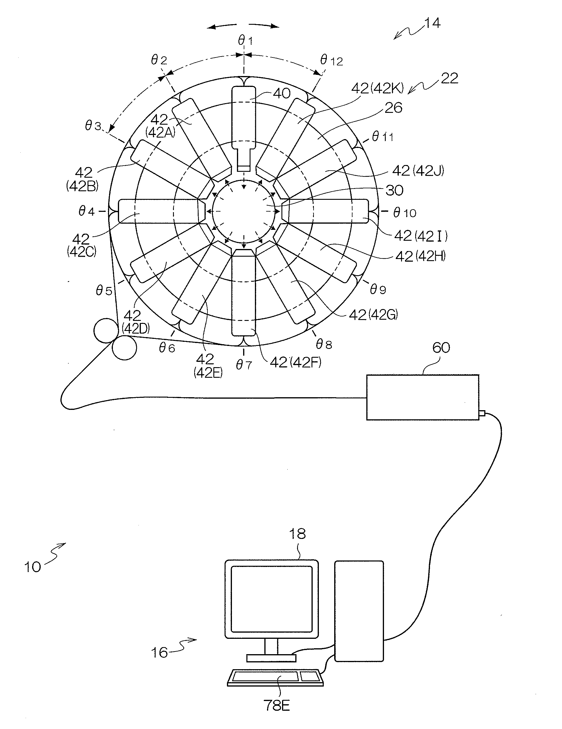
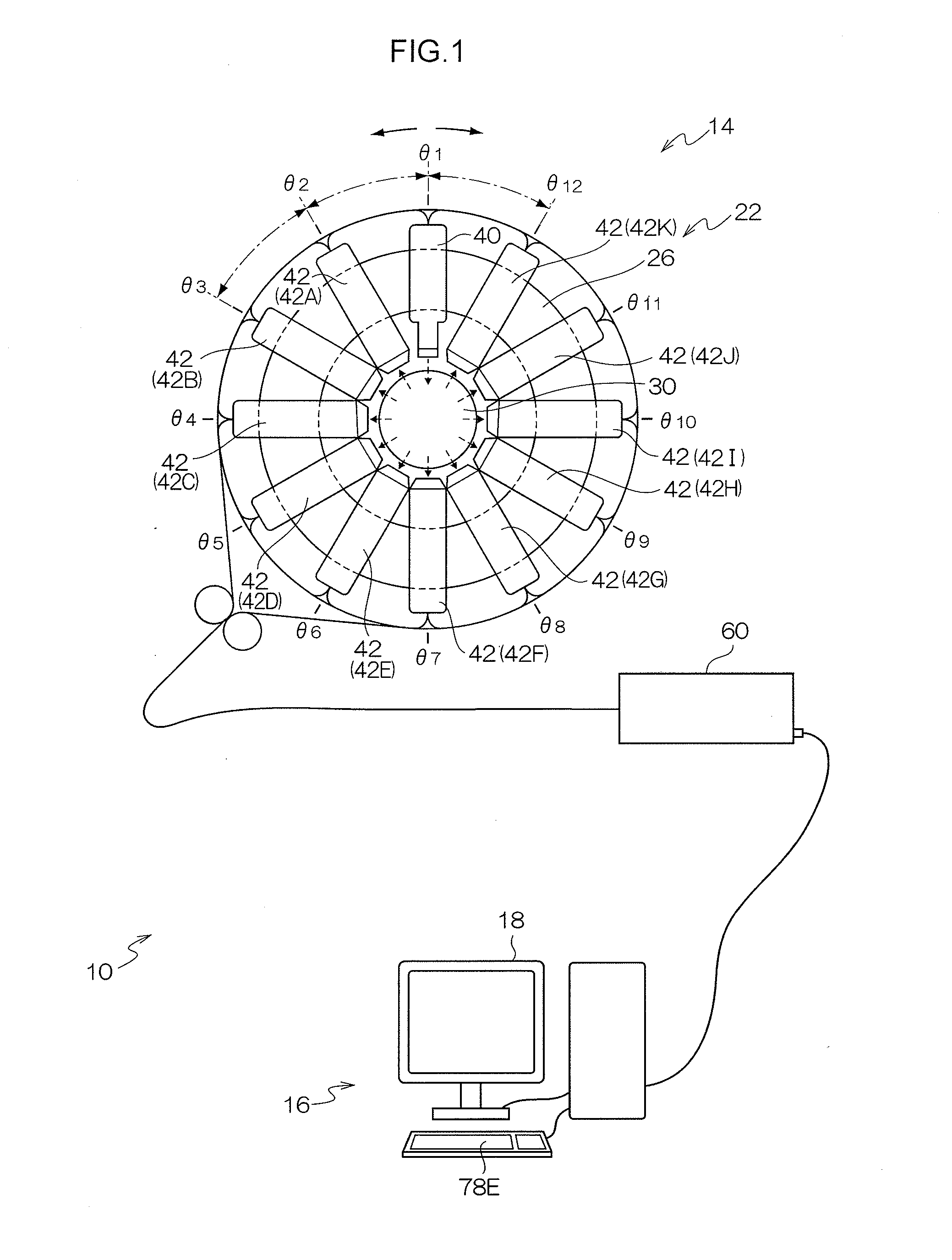
[0050]FIG. 1 to FIG. 6 show an schematic configuration of an optical tomography measurement system 10 according to a first exemplary embodiment. The optical tomography measurement system 10 is configured including an optical measurement device 14 according to the present invention, and a data processing device 16 for performing specific data processing on the measurement data obtained by the optical measurement device 14. Configuration of the optical tomography measurement system 10 may be made with the function of the optical measurement device 14 and the function of the data processing device 16 in an integrated configuration.

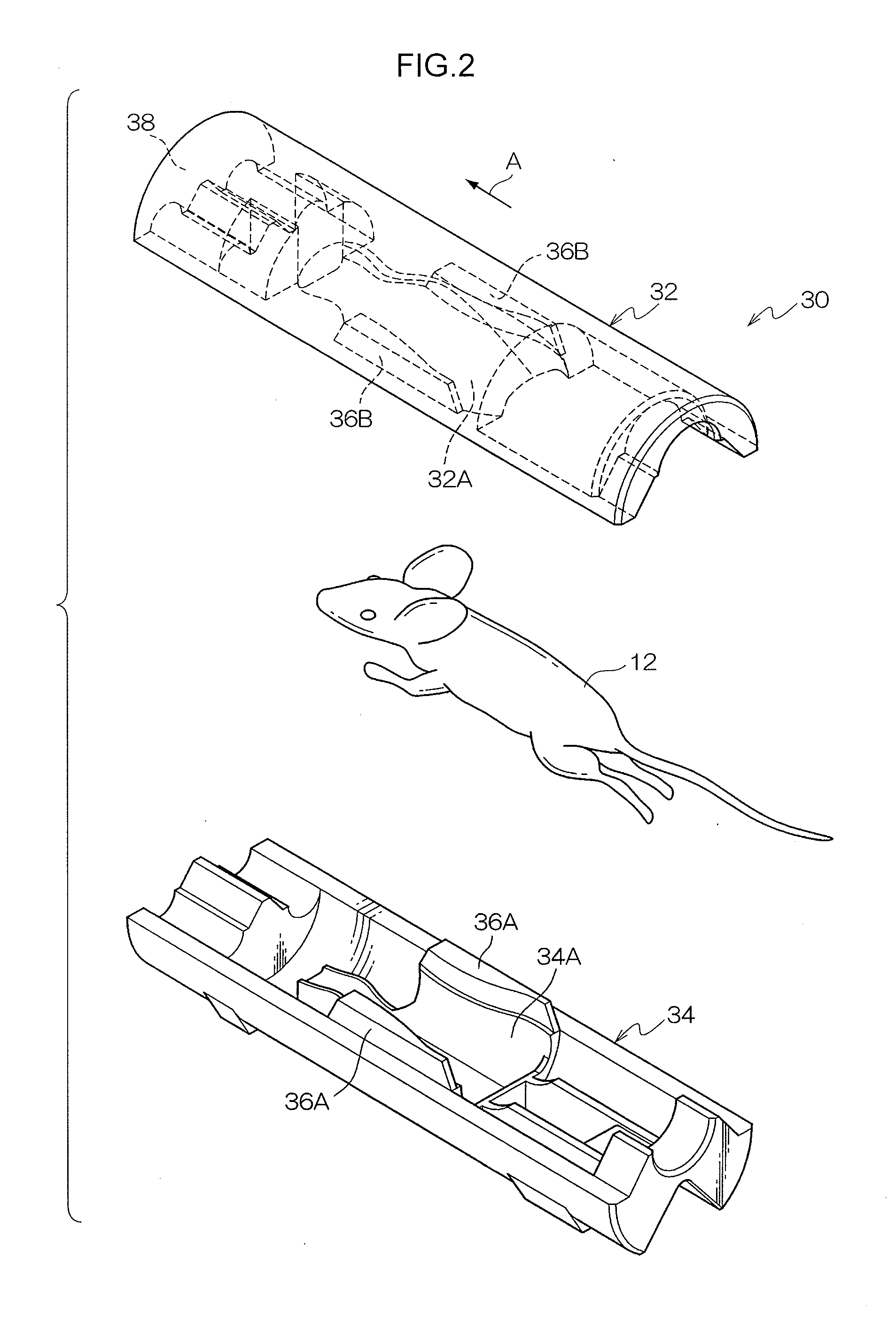
[0051]The optical tomography measurement system 10 has as the measurement subject, for example, a living organism, such as a small animal such as a nude mouse or the like. A fluorescent marking agent (fluorescent substance) is administered to the measurement subject and the optical tomography measurement system 10 reconstructs a tomographic image showing the ...

second exemplary embodiment

[0148]Explanation now follows regarding a second exemplary embodiment. The basic configuration of the second exemplary embodiment is similar to that of the first exemplary embodiment, and similar configurations in the second exemplary embodiment to that of the first exemplary embodiment are allocated the same reference numeral and further explanation is omitted. The second exemplary embodiment employs a light source unit 40A as a reference light source, a light source unit 40B as a first light source, and a light source unit 40C as a second light source, in place of the light source unit 40 of the first exemplary embodiment.

[0149]As shown in FIG. 13, a support shaft 26A is provided to one face of the frame body 26. The support shaft 26A protrudes out in the x axis direction from the frame body 26, and the light source units 40A, 40B, 40C are attached to the support shaft 26A, with the light source unit 40A is attached between the other two. The light source unit 40A illuminates exci...


PUM


Abstract

An optical tomography measurement device that includes an illumination component, a light reception component, a change component, an acquisition component and a correction component is provided. The acquisition component acquires reference data corresponding to an amount of fluorescent light received by the light reception component when an excitation light is illuminated onto the reference position, first data corresponding to the amount of fluorescent light received by the light reception component when the excitation light is illuminated onto a first illumination position, and second data corresponding to the amount of fluorescent light received by the light reception component when the excitation light is illuminated on a second illumination position. The correction component corrects the reference data so as to remove fluorescent light components emitted from a fluorescent marking agent outside of a measurement plane based on the first data and the second data.

Description

CROSS-REFERENCE TO RELATED APPLICATION[0001]This application claims priority under 35 USC 119 from Japanese Patent Application No. 2010-042994 filed on Feb. 26, 2010, the disclosure of which is incorporated by reference herein.BACKGROUND OF THE INVENTION[0002]1. Field of the Invention[0003]The present invention relates to an optical tomography measurement device applied in optical tomography and employed to reconstruct section images of a living organism as a measurement subject.[0004]2. Description of the Related Art[0005]Body tissue has transmissivity to light of specific wavelengths, such as, for example, near infrared radiation. Based on this, Japanese Patent Application Laid-Open (JP-A) Nos. 11-173976 and 11-33 7476 propose performing observations inside living organisms by employing light (optical CT).[0006]In such optical CT, since multiple-scattering occurs when light is being transmitted through the measurement subject, JP-A No. 5-261107 has noticed that there is a differen...

Claims


Application Information

Patent Timeline
Patent Type & Authority Applications(United States)
IPC IPC(8): G01J1/58
CPCA61B5/0071A61B5/0073G01N2021/6465G01N21/6428G01N21/6456G01N21/49A61B5/0062
Inventor TOJO, YU
Owner FUJIFILM CORP
Learn More