Liquid-sealed type vibration isolator

a technology of vibration isolators and liquid seals, which is applied in the direction of shock absorbers, machine supports, mechanical equipment, etc., can solve the problems of not performing the operation of opening and closing of a second orifice flow channel, and achieve the effect of providing inexpensively

Active Publication Date: 2011-09-01
TOYOTA JIDOSHA KK +1
View PDF27 Cites 30 Cited by
  • Summary
  • Abstract
  • Description
  • Claims
  • Application Information

AI Technical Summary

Benefits of technology

[0017]In view of points described above, it is an object of the present invention to provide a liquid-sealed type vibration isolator having a plurality of orifice flow channels which allows switching of characteristics with an inexpensive structure.

Problems solved by technology

However, according to this document, the connecting flow channel is opened when the interior of the main liquid chamber reaches a pressure equal to or below a predetermined value by an input of impulsive heavy-load vibrations, whereby liquid is leaked from the auxiliary liquid chamber to the main liquid chamber to restrain cavitation, but it is not configured to switch the orifice flow channels tuned into different frequencies.
However, according to this document, it is only means to provide the movable membrane with rigidity depending on the amplitude and improve a damping performance in a large amplitude range, but opening and closing operations of a second orifice flow channel are not performed.

Method used


Image

  • Liquid-sealed type vibration isolator
  • Liquid-sealed type vibration isolator
  • Liquid-sealed type vibration isolator

Examples


first embodiment

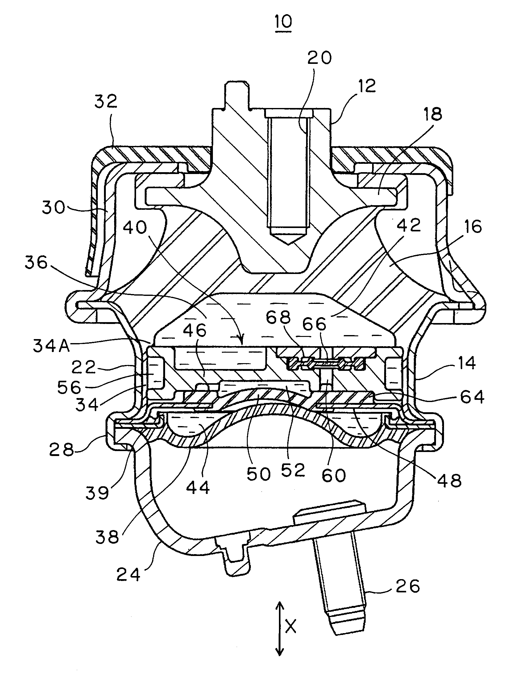
[0074]FIG. 1 is a vertical cross-sectional view of a liquid-sealed type vibration isolator 10 according to an embodiment. The vibration isolator 10 is an engine mount configured to support an engine of an automotive vehicle, and includes an upper first fixture 12 to be fixed to the side of the engine, which is a vibration source, a lower second fixture 14 formed into a cylindrical shape and fixed to a vehicle body on the support side, and a vibration-isolating base member 16 made of a rubber elastomer configured to connect the both fixtures 12, 14 by being interposed therebetween.

[0075]The first fixture 12 is a boss metal fitting arranged at an upper portion of the axial center of the second fixture 14 and is formed with a stopper portion 18 projecting radially outwardly in a flange shape. A bolt hole 20 is provided in an upper end portion, so as to be fixable to the engine side via a bolt, not shown.

[0076]The second fixture 14 includes a cylindrical attachment 22 in which a vibrati...

second embodiment

[0110]FIG. 10 is an enlarged cross-sectional view of a principal portion of the partitioning member 40 in the liquid-sealed type vibration isolator according to a second embodiment. This example is different from the first embodiment in that the annular projecting portions 82 are not provided around the openings 60C and 60D of the valve housing chamber 68, and other configurations are the same as those in the first embodiment and the description is omitted. As regards the effects and advantages, the effects and the advantages on the basis of the annular projecting portions cannot be obtained, other effects and the advantages are the same as those in the first embodiment.

third embodiment

[0111]FIG. 11 is an enlarged cross-sectional view of a principal portion of the partitioning member 40 in the liquid-sealed type vibration isolator according to a third embodiment. In this example, annular projecting portions 84 are integrally formed with the membrane portion 66B of the valve member 66 opposing the peripheral edge portion instead of providing the annular projecting portions 82 on the peripheral edge portions of the openings 60C and 60D of the partitioning member 40.

[0112]The annular projecting portions 84 are formed into a circular shape in plan view so as to surround the openings 60C and 60D over the entire circumference thereof inside the communicating holes 76 and the projections 78 and outside the openings 60C and 60D as shown in FIGS. 11 and 12. More specifically, the annular projecting portions 84 are provided along the outer peripheral portion of the plug portion 66C which closes the openings 60C and 60D, and are provided both on the upper and lower surfaces ...


PUM


Abstract

In a liquid-sealed type vibration isolator having a first orifice flow channel 56 and a second orifice flow channel 60, a valve member 66 formed of a rubber elastomeric membrane for opening and closing the second orifice flow channel 60 is provided on a partitioning member 40 so as to be orthogonal to the direction of flow in the second orifice flow channel. The valve member is held at the outer peripheral portion thereof by a wall surface of a valve housing chamber 68, and includes inside the outer peripheral portion thereof a membrane portion 66B which is subjected to the flexural deformation by the liquid flow in the second orifice flow channel to close openings 60C and 60D of the second orifice flow channel. Communicating holes 76 which bring the second orifice flow channel into communication are provided at positions not overlapped with the opening of the membrane portion 66B. Accordingly, the switching of characteristics is enabled with an inexpensive structure.

Description

TECHNICAL FIELD[0001]The present invention relates to a liquid-sealed type vibration isolator.BACKGROUND ART[0002]As a known vibration isolator such as an engine mount which supports a vibration source such as a vehicle engine or the like so as not to transmit vibrations to a vehicle body side, there is a liquid-sealed type vibration isolator including a first fixture to be fixed to a vibration source side, a second fixture to be fixed to a support side, a vibration-isolating base member provided between these fixtures and made of elastomer, a main liquid chamber having a chamber wall formed partly of the vibration-isolating base member, an auxiliary liquid chamber having a chamber wall formed partly of a diaphragm, and an orifice flow channel configured to communicate these liquid chambers, and configured to carry out a vibration damping function and a vibration insulating function by a liquid flow effect due to the orifice flow channel or by a vibration control effect due to the v...

Claims


Application Information

Patent Timeline
Patent Type & Authority Applications(United States)
IPC IPC(8): F16F13/10F16F13/08
CPCF16F13/106
Inventor YAMAMOTO, KENTAROOHGUCHI, TAKAHIROISAWA, GENHASE, KENGOFURUSAWA, NORIMITSUSAKURAI, KATSUHIRO
Owner TOYOTA JIDOSHA KK
Why Eureka
Try Eureka