
Adjustable steering column for motor vehicles

a technology for steering column and motor vehicles, applied in the direction of steering column, steering parts, vehicle components, etc., can solve the problems imposing the use of structurally distinct, and hindering the implementation of the energy-absorbing mechanism. , to achieve the effect of reducing the number of pieces

Active Publication Date: 2011-09-01
ROBERT BOSCH AUTOMOTIVE STEERING VENDOME SAS
View PDF9 Cites 46 Cited by
  • Summary
  • Abstract
  • Description
  • Claims
  • Application Information

AI Technical Summary

Benefits of technology

[0018]Advantageously, the ratchet mechanism is arranged to cooperate directly with the plastically deformable element during its plastic deformation. Thus, this enables to limit the number of pieces that are necessary for the implementation of the energy dissipation, and hence to reduce the cost and time necessary for the assembly of the pieces of the steering column.
[0020]Advantageously, the pawl is associated to the adjustment and locking means such that, when the adjustment and locking means switch from an adjusting state to a locked state, the pawl switches from a released position to a position in which it contacts the guide strip. Thus, this configuration makes it possible, when acting on the adjustment and locking means, to act simultaneously on the ratchet mechanism.
[0021]According to a particularly advantageous configuration, the ratchet mechanism comprises elastic means to engage the pawl with the guide strip during the plastic deformation of the plastically deformable element. Thus, this makes it possible to permanently maintain the contact of the pawl against the guide strip on the one hand and to engage the pawl with the guide strip during an impact imparted to the tubular body on the other hand. Elastic means may be provided so as to be formed of one single piece with the pawl.
[0027]Advantageously, the guide strip is fixed to the tubular body by means of a shearing dowel. The shearing dowel enables additional energy absorption than that generated by the plastically deformable element.
[0028]According to a specific configuration, the plastically deformable element consists of a guide strip arranged in the extension of the guide strip. In order to reduce the number of pieces, it may be advantageous to provide a strap and a guide strip forming one same and single piece.

Problems solved by technology

However, the device described in this document, shows the drawback of imposing the use of structurally distinct members in order to obtain a device which fulfills both the energy absorption function and the axial retention function.
A major drawback is the number of pieces necessary for implementing the device combining the functions for adjusting the steering column and for energy dissipation, and more particularly essential for maintaining the locking means locked together, depending on whether the locking situation is a collision-free locking situation or a locking situation without collision.
However, when a collision occurs, due to the fact of the retraction of the tubular body into the support member, the spring forming member is no longer in contact with the cam element.
Such friction would in fact hinder the implementation of the energy-absorption mechanism.
Finally, due to the fact that the shaft around which the elongated guide strip forming the energy-absorption device may be pulled is secured to the support member and that the locking means are carried by the tubular body during the retraction of the tubular body, the absorption of energy is not always ensured at the start of the tubular body retraction.
Due to the fact of the number of pieces necessary for mounting the member enabling the energy absorption between the support assembly and the tubular body of the steering column, the assembling of the previously described absorption device to a steering column proves to be somewhat difficult.

Method used


Image

  • Adjustable steering column for motor vehicles
  • Adjustable steering column for motor vehicles
  • Adjustable steering column for motor vehicles

Examples


Embodiment Construction

)

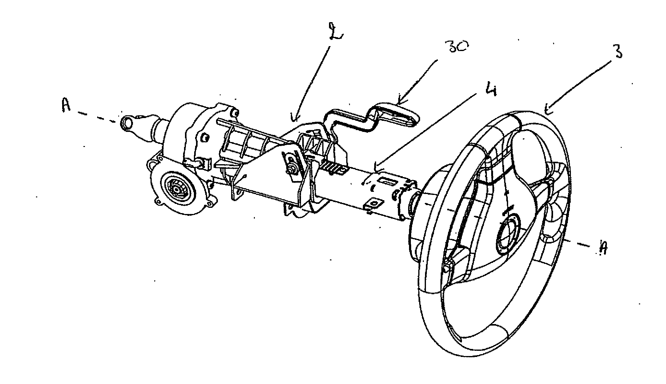
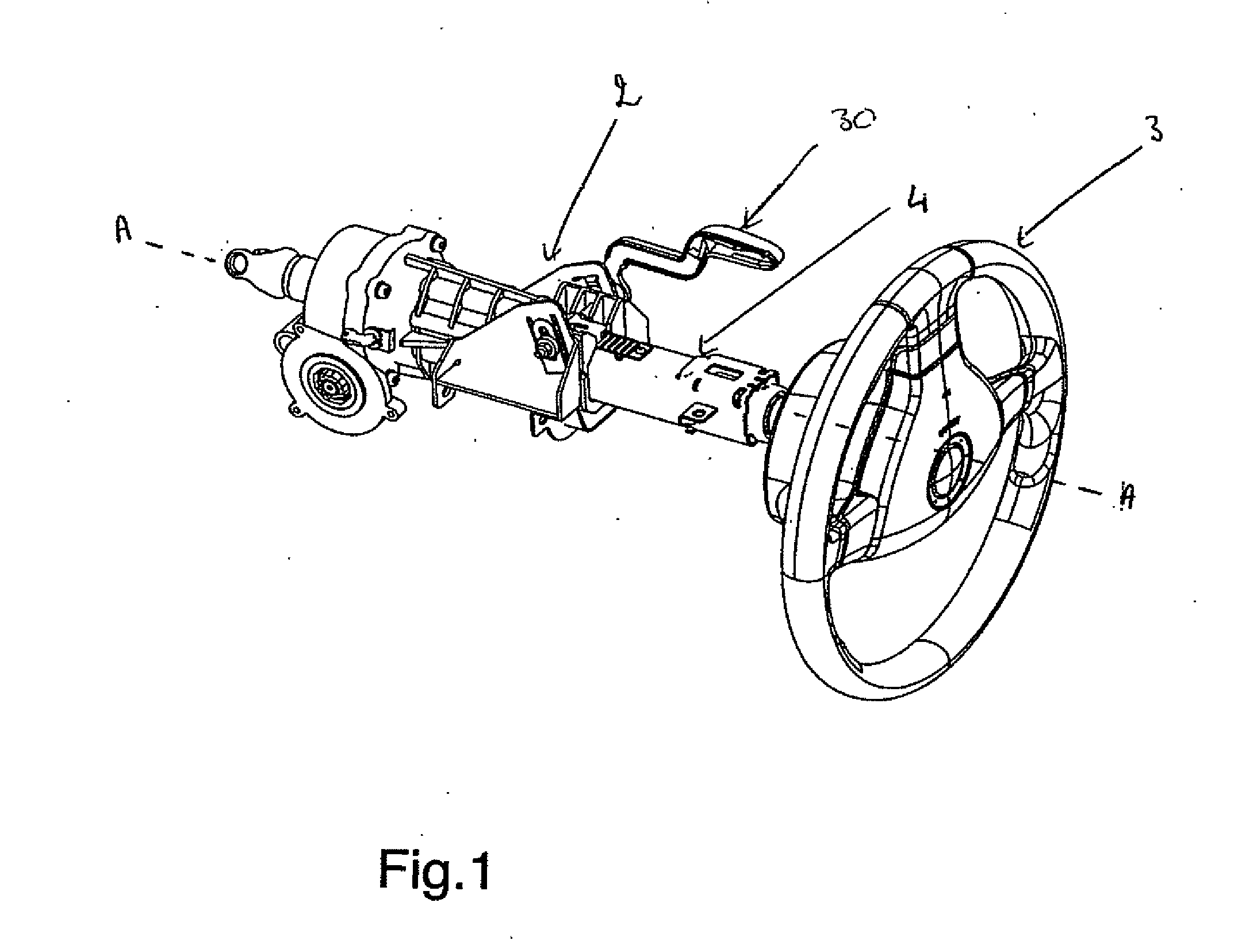
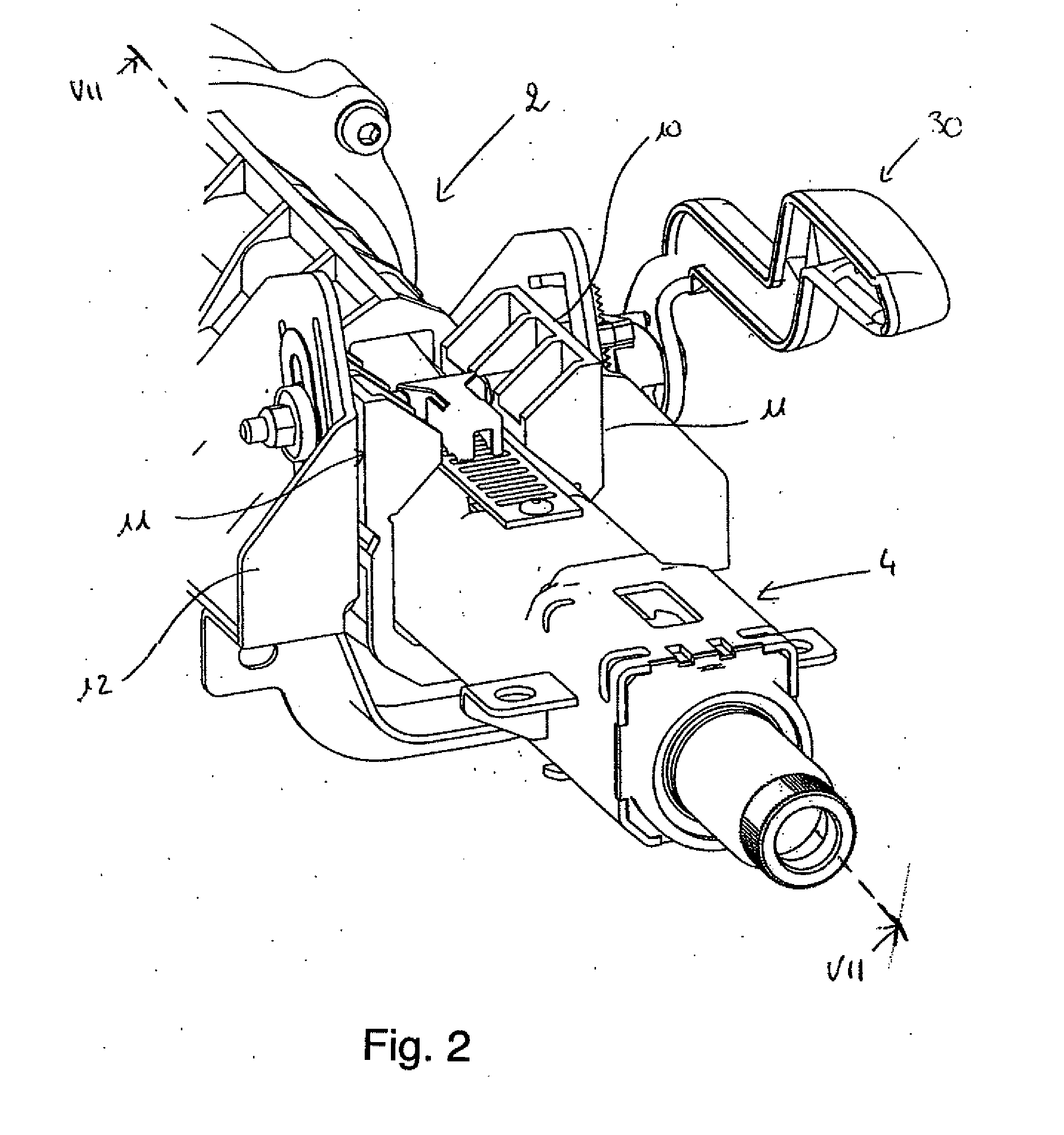
[0042]In relation to FIGS. 1 to 8, it has been described a steering column 1 for motor vehicle, the steering column being adjustable at least axially.

[0043]The steering column 1 comprises a support assembly 2 intended to be fixed on a chassis of a vehicle (not shown) and a tubular body 4, of longitudinal axis AA, whereon the vehicle steering wheel 3 is fixed, as shown in FIG. 1. The tubular body 4 is slidably mounted in the support assembly 2 such as to enable the adjustment of the steering wheel (axial adjustment) depth by sliding the tubular body 4 into the support assembly 2.

[0044]In order to maintain the steering wheel according to the required depth, the steering column 1 comprises adjustment and locking means able to switch from a state of adjusting the position of the tubular body 4 inside the support assembly 2 to a state of immobilizing the tubular body in a desired adjusted position inside the support assembly 2.

[0045]In the described embodiment, the adjustment and lockin...


PUM


Abstract

An adjustable steering column for a motor vehicle has a support assembly intended to be fixed to a chassis of a vehicle, a tubular body slidably mounted in the support assembly, adjustment and locking devices able to switch from a state of a adjusting the position of the tubular body in the support assembly to a state of immobilizing the tubular body in a desired adjusted position within the support assembly, a plastically deformable energy-absorbing element collaborating with a deformation member secured to the tubular body so that it undergoes plastic deformation as the tubular body retracts inside the support assembly following an impact transmitted to the tubular body when the adjustment and locking devices are in the locked state and a ratchet mechanism for securing the plastically deformable element to the support assembly during plastic deformation of the plastically deformable element.

Description

BACKGROUND OF THE INVENTION[0001]1. Field of the Invention[0002]The invention relates to an adjustable steering column for motor vehicles.[0003]More particularly, the invention relates to a depth-adjustable (axial adjustment) or depth and height-adjustable (axial and radial adjustment) steering column, the steering column comprising a tubular body slidably mounted in a support assembly, means for adjusting the position of the tubular body in the support assembly and for locking in the desired position, as well as a device enabling to dissipate or absorb the energy generated during a frontal collision of the vehicle with an obstacle, following an impact of the driver on the steering column.[0004]2. Prior Art[0005]The implementation of energy-absorption devices on steering columns is known per se. By way of example, it is worth quoting the patent application GB 2 281 539. However, the device described in this document, shows the drawback of imposing the use of structurally distinct me...

Claims


Application Information

Patent Timeline
IPC IPC(8): B62D1/19B62D1/184
CPCB62D1/195B62D1/184
Inventor MONTEIL, PASCALGENET, NICOLASORIAC, ANTOINE
Owner ROBERT BOSCH AUTOMOTIVE STEERING VENDOME SAS
Learn More