Multiple liquid lens driver

a liquid lens and driver technology, applied in the field of multi-liquid lens drivers, can solve the problem of large surface area of integrated circuits or circuit boards

Inactive Publication Date: 2011-09-01
VARIOPTIC SA
View PDF3 Cites 44 Cited by
  • Summary
  • Abstract
  • Description
  • Claims
  • Application Information

AI Technical Summary

Problems solved by technology

However, such circuits are designed to drive only one pair of electrodes in a single lens.
However, this solution is disadvantageous as it is costly, and consumes a large surface area of an integrated circuit or circuit board.

Method used


Image

  • Multiple liquid lens driver
  • Multiple liquid lens driver
  • Multiple liquid lens driver

Examples


Embodiment Construction

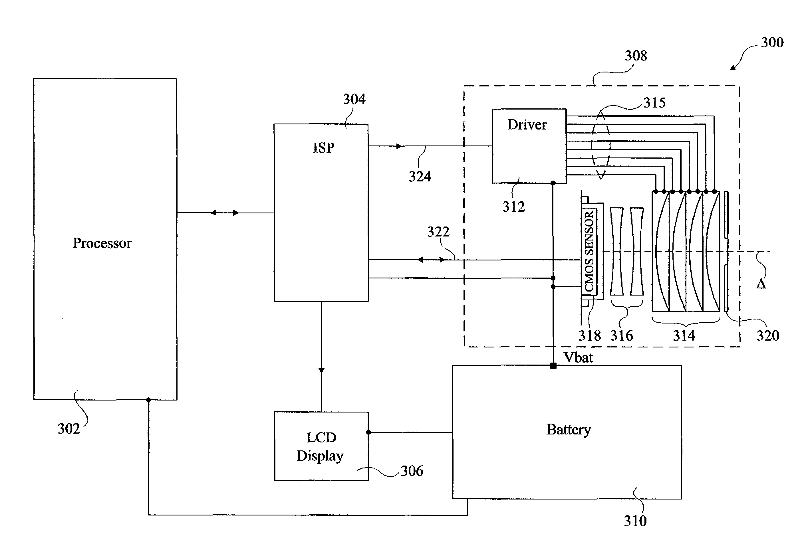
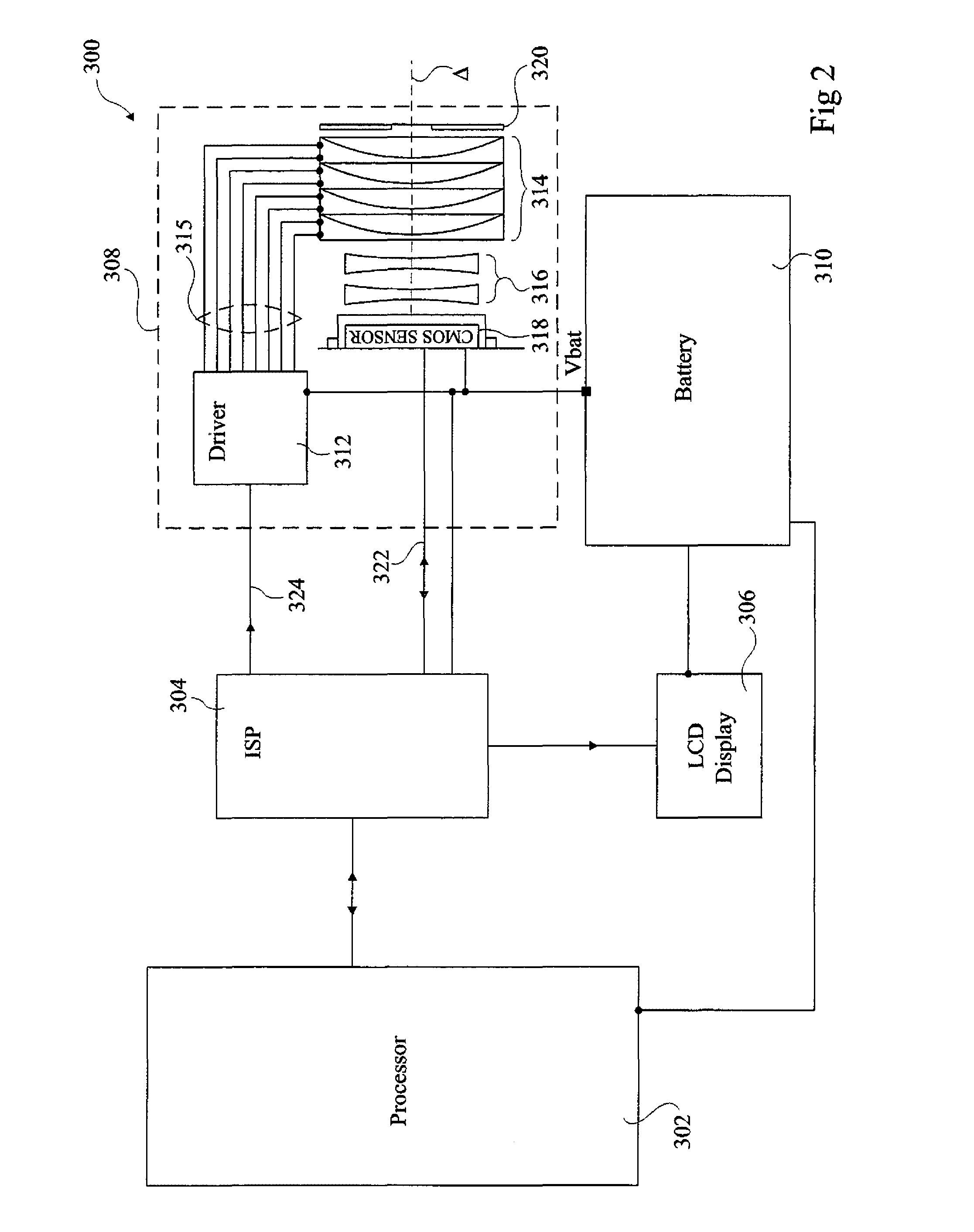
[0032]FIG. 2 illustrates an optoelectronic module 300 comprising a plurality of liquid lenses. Module 300, which is for example incorporated in a mobile telephone, comprises a processor 302, which is for example the baseband processor of a mobile phone, an image signal processor (ISP) 304, LCD display 306, a lens module 308 and a battery 310 which is for example a mobile phone battery.

[0033]Lens module 308 comprises a driver circuit 312, for driving the plurality of variable focus liquid lenses 314. In this example four liquid lenses are provided, one of which is used for focusing, a second for zooming, and third and fourth lenses for the correction of chromatic and field curvature aberrations. In alternative embodiments, different liquid lens arrangements having a different number of liquid lenses could be driven.

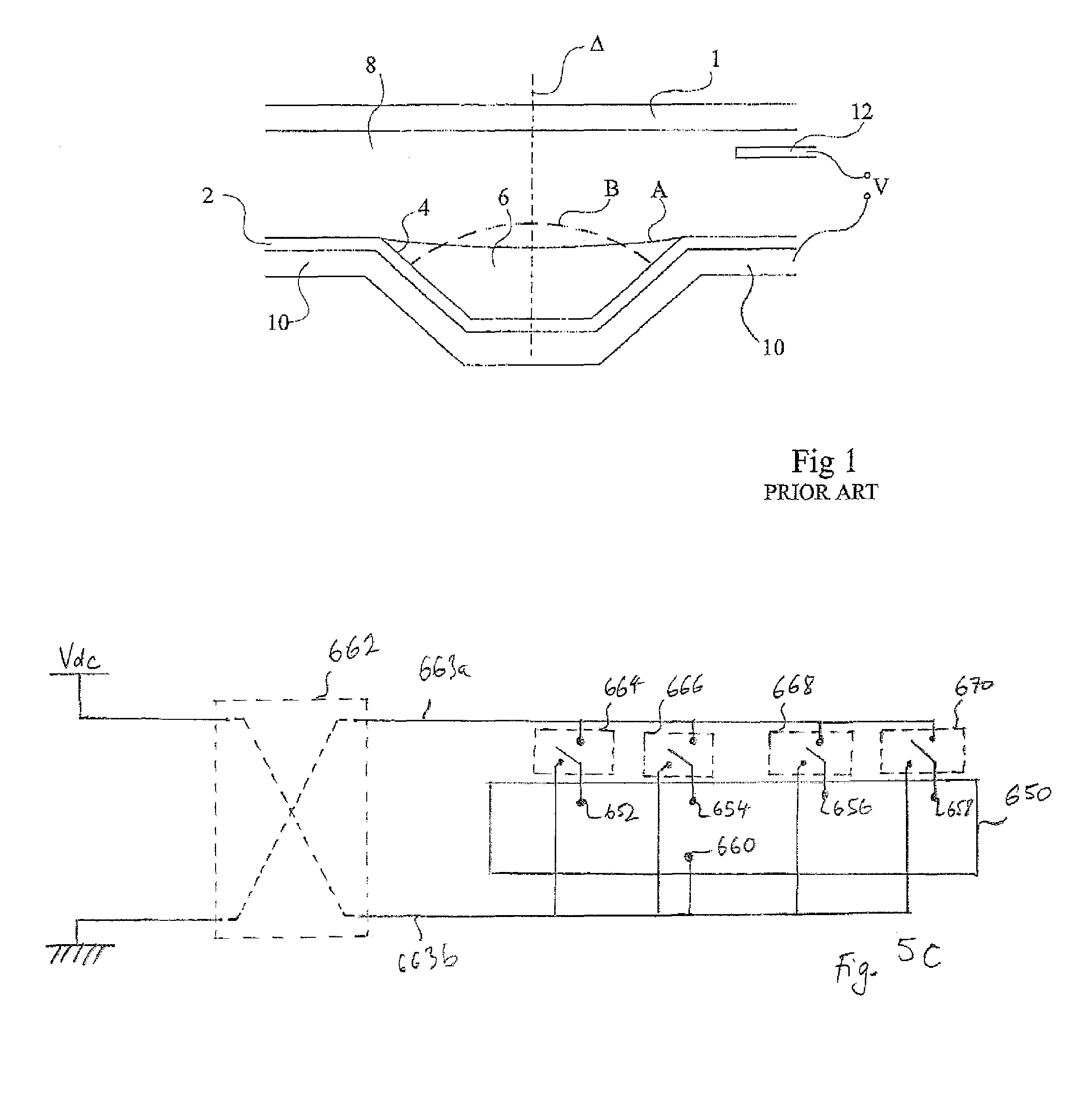
[0034]The variable focus liquid lenses 314 are for example liquid lenses as described in relation to FIG. 1 above, or any similar liquid lens having a focus variable by ap...


PUM


Abstract

The invention concerns drive circuitry for generating a plurality of independent drive voltage signals for a plurality of electrodes of at least one liquid lens, the liquid lens comprising first and second miscible liquids, an interface between the first and second liquids being movable by electro wetting by application of a drive voltage signal to at least one electrode of the liquid lens, the drive circuitry including generating circuitry (406, 408, 410, 412) arranged to generate a fixed drive voltage (Vdc); a duty cycle controller (418) arranged to receive data values indicating a duty cycle to be applied to each of the plurality of electrodes, and to generate a control timing signal for each of the plurality of electrodes, each control timing signal having the duty cycle indicated by the controller; and driving means (426, 428, 430, 432) arranged to generate an independent drive voltage signal for each of the plurality of electrodes by selectively applying the fixed drive voltage, based on the control timing signal associated with each liquid lens.

Description

FIELD OF THE INVENTION[0001]The present invention relates to a circuit for driving the electrodes of one or more liquid lenses, and in particular to a driving circuit for driving electrodes of liquid lenses having liquids moveable by electrowetting.BACKGROUND OF THE INVENTION[0002]A number of embodiments of variable focus liquid lenses are described in European patent N° 1166157.FIG. 1 of the present application corresponds to FIG. 12 of that patent and illustrates an example of a variable focus liquid lens according to the prior art. As shown in FIG. 1, a variable focus lens comprises a fluid chamber with two insulating transparent plates 1 and 2 and an optical axis Δ. Plate 2 comprises a conical or cylindrical recess, with a side face 4 inclined with respect to the optical axis Δ of the device, and which receives a drop of a first liquid 6 which is an insulating liquid. The remainder of the chamber extending up to transparent plate 1 is filled with a second liquid 8, which is cond...

Claims


Application Information

Patent Timeline
Patent Type & Authority Applications(United States)
IPC IPC(8): G02B3/14
CPCG02B26/005G02B3/14G02B26/02G02F1/133G09G3/18
Inventor CRAEN, PIERREMORICHAUD, GWENAEL
Owner VARIOPTIC SA
Why Eureka
Try Eureka