Spinal Implant

a technology of spine and implant, applied in the field of spine implants, can solve the problems of increasing severity of problems, complex locking components, and large package size and implant locking, and achieve the effect of sufficient friction

Inactive Publication Date: 2011-09-01
INTELLIGENT IMPLANT SYST
View PDF77 Cites 33 Cited by
  • Summary
  • Abstract
  • Description
  • Claims
  • Application Information

AI Technical Summary

Benefits of technology

[0012]In addition, the present invention further provides a method of fixing a rod to a screw head by seating a screw head having multiple contact points in a screw seat of a body portion causing the screw head to interfere with and contact multiple portions of the spherical seat creating sufficient friction to lock the screw head in a desired position during rod insertion while allowing the body portion to rotate relative to the screw head.

Problems solved by technology

This problem increases in severity with an increasing number of screw assemblies that the surgeon is trying to connect to the same rod.
The main problems with polyaxial screws are package size and implant locking.
For all of these implants, and a few that are small in size, the locking component is complex and often involves the use of threads.
Finding a thread inside the implantation site is difficult and creates issues such as cross-threading.
However, once assembled, the screw is no different than the other prior art.
This approach also has limitations in the amount of allowable rotation in all directions, as the edges of the head contact the rod when the head is rotated.
This complex design requires compression of the disk-like projection in a taper.
The difficulties in this are high because when the screw head rotates, only a small portion of the disk-like projection is in contact with the taper, thereby making it almost impossible to lock the angulation of the screw in position.
In addition, this design is restricted to a curvate screw head.

Method used


Image

  • Spinal Implant
  • Spinal Implant
  • Spinal Implant

Examples


Embodiment Construction

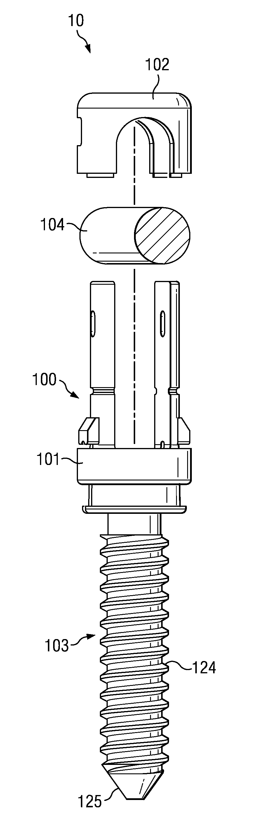
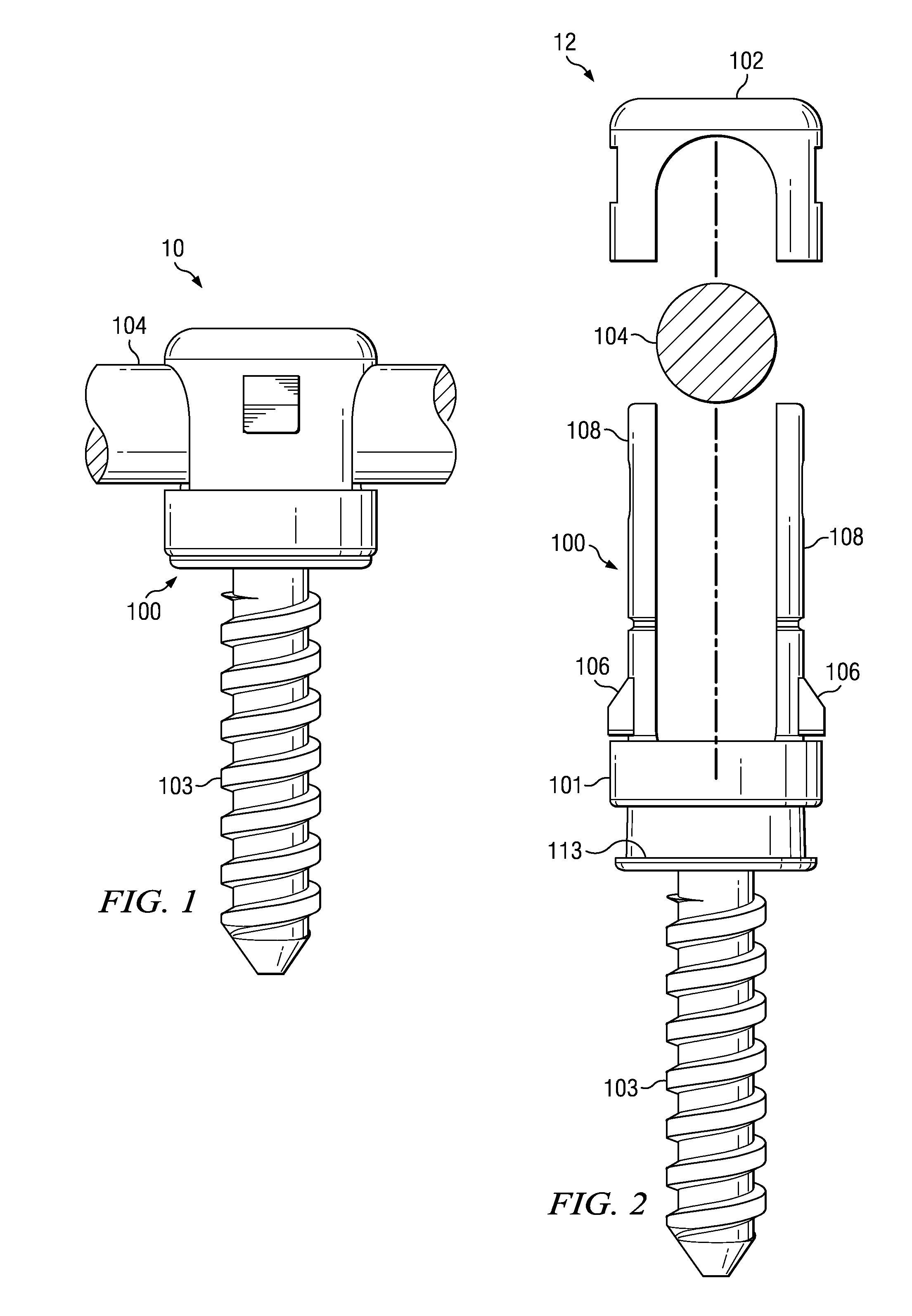
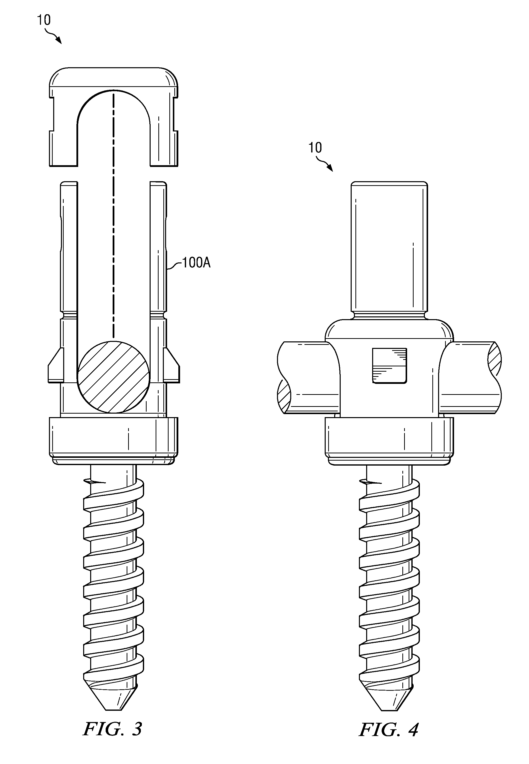
[0041]In accordance with the present invention, a screw and rod fixation assembly is generally shown at 10 in the figures. Most generally, the assembly includes a body member 100 including a screw seat 119 for seating a screw head therein and a rod seat 116 for seating a rod 104 therein. An adjustable rod locking mechanism in the form of a rod locking member 102 adjustably applies a locking force against a rod 104 seated in the rod seat 116. An adjustable screw locking mechanism in the form of a screw locking ring 101 adjustably applies a locking force to a screw head seated in the screw seat 119. The adjustable screw locking mechanism is functionally independent of the adjustable rod locking mechanism. Thus, in use, a practicing physician can independently adjust the body member relative to the screw and, independently, relative to the rod. This provides the physician with much more flexibility during surgery, as described in more detail below.

[0042]More specifically and referring ...


PUM


Abstract

A screw and rod fixation assembly includes a body member including a screw seat for seating a screw head therein and a rod seat for seating a rod therein. An adjustable locking ring applies a locking force against the screw head seated in the screw seat and a locking cap adjustably applies a locking force against a rod seated in the rod seat. The adjustable screw locking ring and locking cap function independent of each other.A method of fixing the rod to the screw includes the steps of inserting a screw head into a screw seat in one end of a body member and inserting a rod into a rod seat in a second end of a body member and selectively and independently adjusting a locking force on both the screw head and the rod within the screw seat and rod seat, respectively.

Description

RELATED APPLICATION[0001]This application is a continuation application of U.S. application Ser. No. 11 / 876,890 which was filed Oct. 23, 2007, the contents of which are incorporated herein by reference as if set forth in full.TECHNICAL FIELD[0002]The present invention generally relates to spinal implants. More particularly, the present invention relates to screw fixation assemblies for use with bone fixation systems.BACKGROUND ART[0003]Polyaxial screw implants for assisting in fusion surgeries have been in use for many years. Typically, polyaxial screw motion implants allow motion of a body portion around a spherical screw head to allow the assembly to pivot. When individual screw assemblies are connected by a rod, it is common for the rod to be out of alignment with all of the screw assemblies. This problem increases in severity with an increasing number of screw assemblies that the surgeon is trying to connect to the same rod. Pivoting allows the assembly to compensate for this pr...

Claims


Application Information

Patent Timeline
Patent Type & Authority Applications(United States)
IPC IPC(8): A61B17/70A61B17/88A61B17/86
CPCA61B17/7032A61B2019/307A61B17/7037A61B17/7035A61B2090/037
Inventor RICHELSOPH, MARC
Owner INTELLIGENT IMPLANT SYST
Why Eureka
Try Eureka