
Sand and Fluid Production and Injection Modeling Methods

a technology of fluid production and injection modeling, which is applied in the direction of analogue processes, instruments, and borehole/well accessories for specific applications, etc., can solve the problems of low recovery ratio, difficult operation and maintenance, and limited recovery of bitumen using water injection techniques

Inactive Publication Date: 2011-09-01
EXXONMOBIL UPSTREAM RES CO
View PDF40 Cites 39 Cited by
  • Summary
  • Abstract
  • Description
  • Claims
  • Application Information

AI Technical Summary

Problems solved by technology

Other methods breakup the sand matrix in which the heavy oil is entrained by water injection to produce the formation sand with the oil; however, the recovery of bitumen using water injection techniques is limited to the area proximal the bore hole.
These methods generally have low recovery ratios and are expensive to operate and maintain.
Efficiently and effectively recovering these resources for use in the market is one of the world's toughest energy challenges.
In cases of CSS and SAGD, sand production is not desirable.
These methods are not suitable to evaluate the interaction between the reservoir, injected material and the surrounding formation.
These models do not simulate actual sand production.
These models also fail to account for addition or removal of material (e.g., sand) to or from the reservoir.
This model also fails to simulate the removal of material from the reservoir.
However, when sand production rates are large (e.g., in the FIRE process) these models are generally inaccurate.
Moreover, these methods do not address the simulation of injection of sand and slurry back into the sub-surface.
These coupled models may simulate injection of fluids, but they do not simulate injection of solids into reservoir.
These coupled models simulate interaction between reservoir solids and fluids when deformation experienced by solids is small and they are not suitable for simulating very large strains which are common when significant portions of the reservoir sand is produced in processes like FIRE.

Method used


Image

  • Sand and Fluid Production and Injection Modeling Methods
  • Sand and Fluid Production and Injection Modeling Methods
  • Sand and Fluid Production and Injection Modeling Methods

Examples


examples

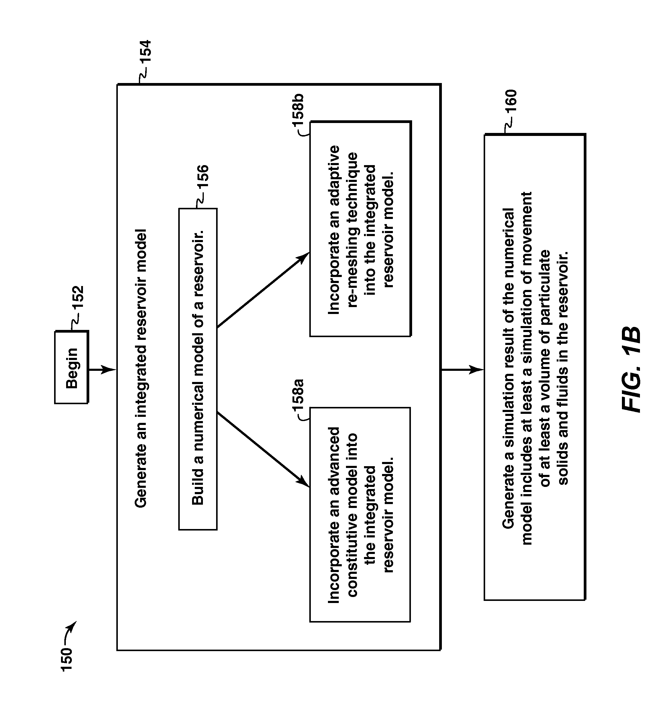
[0064]The following example shows the combined use of automatic mesh refinement 158b, EBC 108, and large strain formulations of geomechanics and fluid flow formulations 158a for simulating large sand / water production and injection volumes. The following analyses were carried out using the ELFEN (Rockfield 2007) suit of finite element software.

[0065]A hypothetical formation 300 of 60 m wide, 60 m long and 10 m thick was selected. There are four injectors 302 at four corners, 60 m from each other, and a producer 304 in the middle (e.g., a “five spot” pattern). A ⅛th symmetrical model 306 of the formation 300, using appropriate boundary conditions, is sufficient to represent the entire formation 300. The ⅛th symmetrical model 306 includes the overburden 308 and the underburden 310 above and below the reservoir 312. The radii of injector 302 and producer 304 were assumed to be 1 m.

[0066]The first step in the analyses is conditioning of reservoir 312, which can be simulated using solid-f...


PUM


Abstract

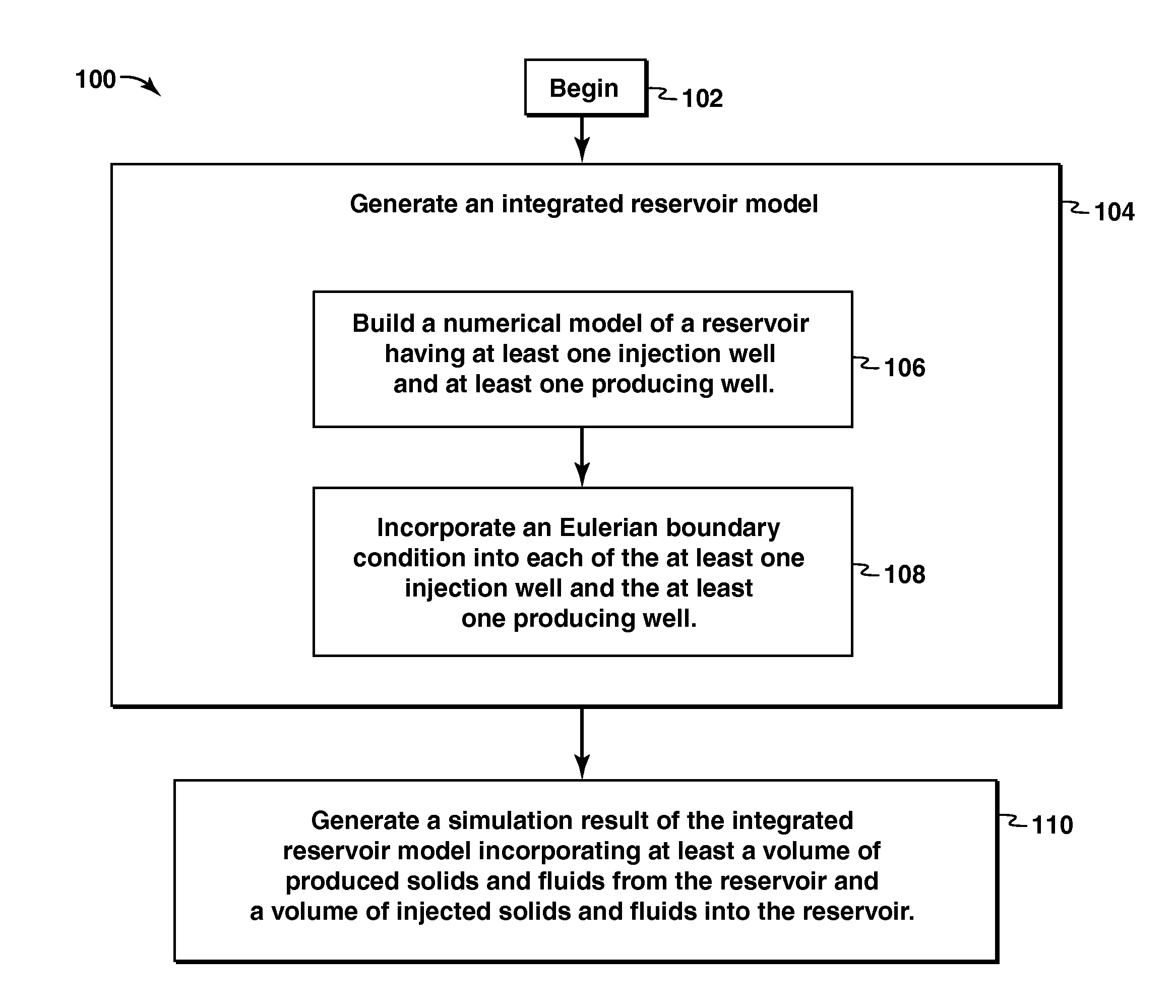
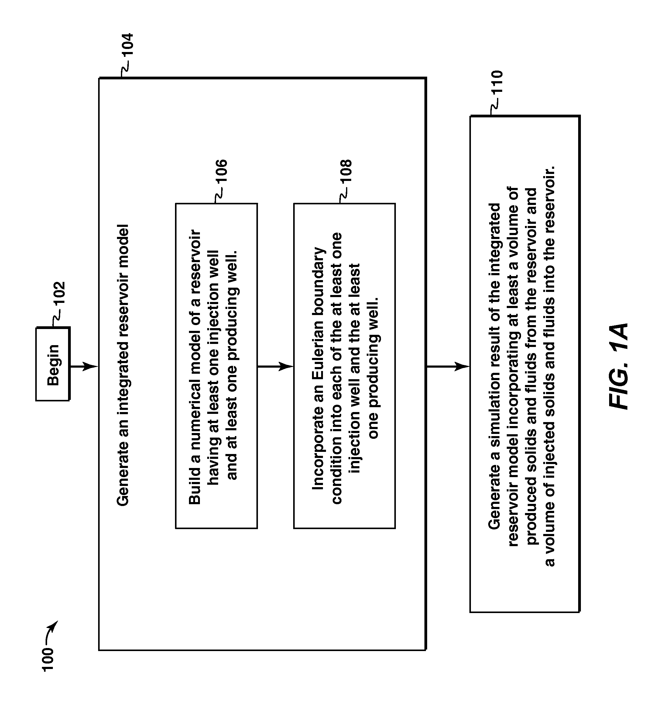
Methods for modeling subsurface reservoirs are provided. In at least one embodiment, the process includes building a numerical model of a reservoir having at least one injection well and at least one producing well, and incorporating at least one of an Eulerian boundary condition (EBC) into each of the at least one injection well and at least one producing well, an advanced constitutive model (ACM) int the reservoir, and an adaptive re-meshing technique (ART) into the reservoir model. Then generating a simulation result from the integrated reservoir model, wherein the simulation result includes at least a volume of produced fluids and produced particulate solids from the reservoir, a volume of injected fluids and injected particulate solids into the reservoir, and a simulation of movement of at least a volume of particulate solids and fluids in the reservoir.

Description

CROSS REFERENCE TO RELATED APPLICATIONS[0001]This application claims the benefit of U.S. Provisional Application No. 61 / 116,549, filed 20 Nov. 2008.FIELD OF THE INVENTION[0002]Embodiments of the invention relate to methods of modeling sand and fluid production from a subsurface formation, and sand and fluid injection into a subsurface formation. More particularly, embodiments of the invention relate to methods for modeling reservoirs using numerical analysis to more accurately predict reservoir behavior during production and injection of sand and fluids.BACKGROUND OF THE INVENTION[0003]This section is intended to introduce various aspects of the art, which may be associated with exemplary embodiments of the present invention. This discussion is believed to assist in providing a framework to facilitate a better understanding of particular aspects of the present invention. Accordingly, it should be understood that this section should be read in this light, and not necessarily as admis...

Claims


Application Information

Patent Timeline
IPC IPC(8): G06G7/48
CPCE21B43/00G06F30/23G06F2111/10
Inventor DASARI, GANESWARA R.YALE, DAVID P.WANG, JIANLIN
Owner EXXONMOBIL UPSTREAM RES CO
Learn More