Method of user display associated with displaying registered images

Inactive Publication Date: 2011-09-01
VANBREE KEN
View PDF10 Cites 12 Cited by
  • Summary
  • Abstract
  • Description
  • Claims
  • Application Information

AI Technical Summary

Benefits of technology

[0005]The invention taught herein meets at least all of the recited unmet needs. The invention provides a method that enables a User to enter a structure/building under construction, on a computer enabled device, display a floorplan or map of the realworld structure in which User is standing, and User can indicate on the display, via a mouseclick, for example, the User's approximation of U

Problems solved by technology

Without such a capability the number of images taken at a construction site can quickly overwhelm their usefulnes

Method used


Image

  • Method of user display associated with displaying registered images
  • Method of user display associated with displaying registered images
  • Method of user display associated with displaying registered images

Examples


Embodiment Construction

[0020]The invention provides a means to display to the User a floorplan of interest and a fairly accurate indication and storage of a viewport, stored and retrievable along with any images associated with that viewport, where the viewport appears as an icon on a depiction of the floorplan displayed to User.

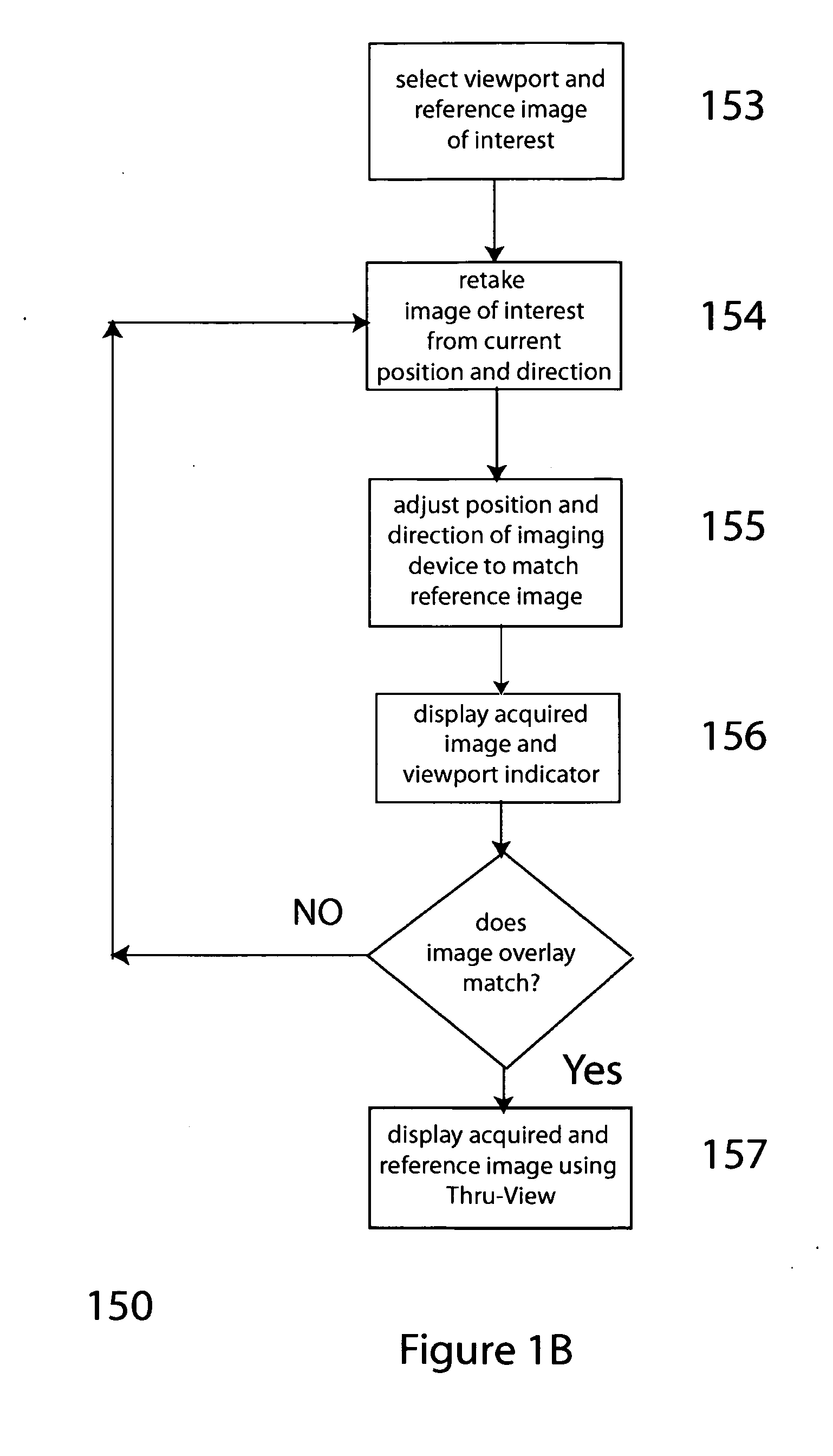
[0021]In an alternate embodiment the invention provides a means to precisely align images taken from viewports as represented on the floor plan displayed to User, so that a thru-view viewing is possible, as taught in another US patent (entitled “System for Accurately Repositioning Imaging Devices”)

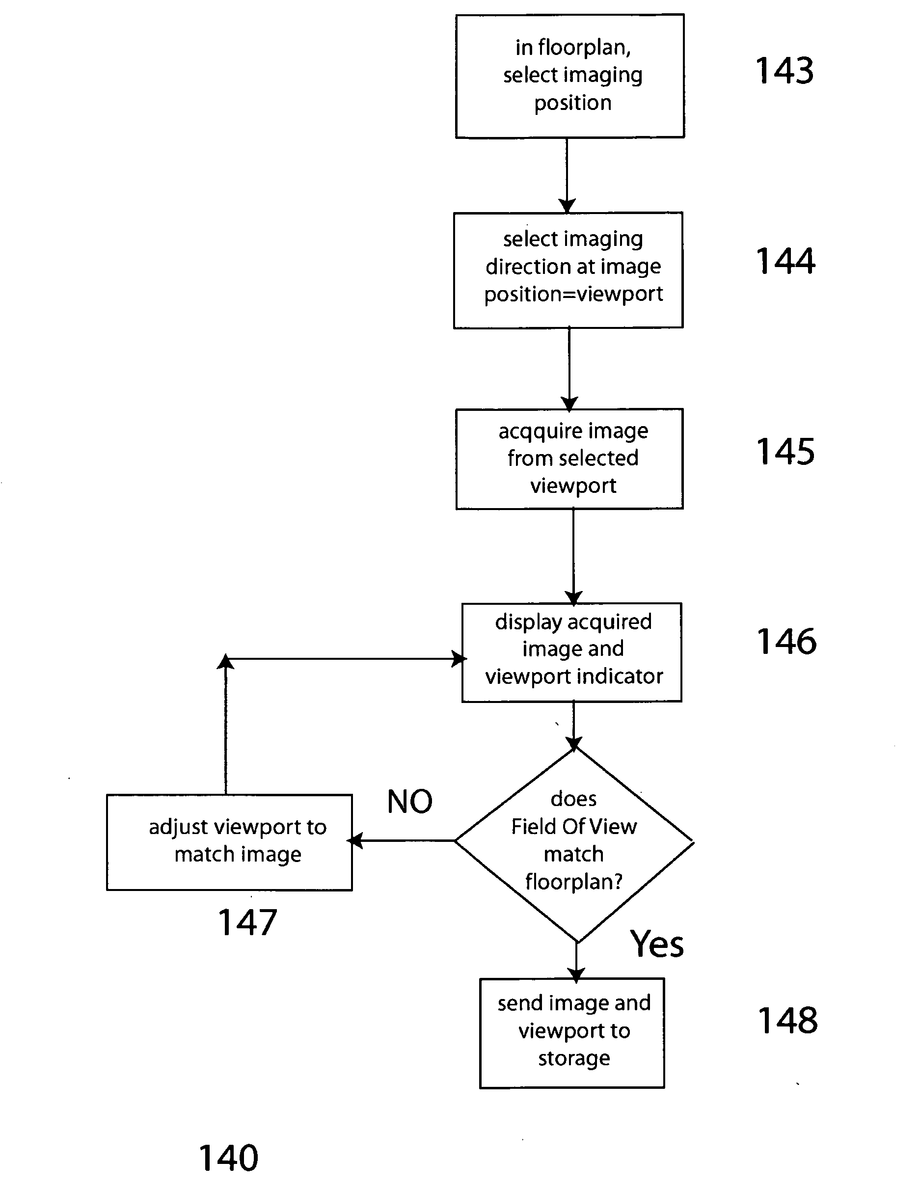
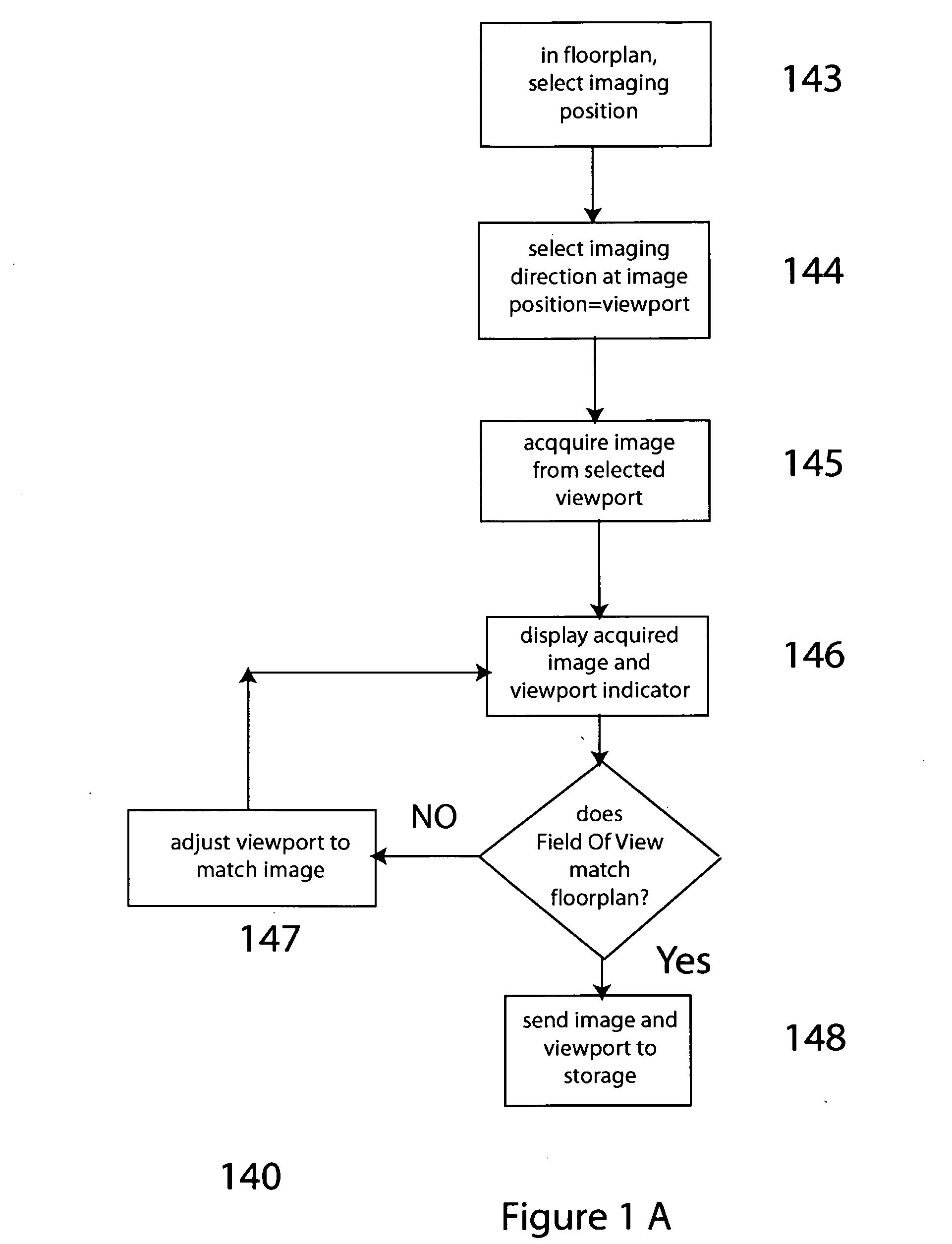
[0022]Referring now to FIG. 1A a preferred embodiment of the invention provides the method 140 which comprises the step of:

selecting a floorplan, and an area of interest on floor plan, and selecting a first imaging position within the floor plan 143;

selecting a first imaging direction at a first imaging position 144, which comprise a viewport;

acquiring image from location corresponding t...


PUM


Abstract

The invention provides a means for a User to enter a structure/building under construction, on a computer enabled device, display a 2D floorplan or map of the realworld [3D] structure in which User is standing, and User can indicate on the display, via a mouseclick, for example, the User's approximation of User's realworld location. Then, User can acquire an image, and the display will indicate to User how to more accurately select the position from which the image was acquired. The information—i.e. both the acquired image and the imaging position information on the floorplan—can be stored, and retrieved and re-displayed, by clicking the interactive floorplan of the structure.
In an alternate embodiment, the invention provides that in addition to an acquired image, User may retrieve a reference image, and compare the acquired image with the reference image, and refine the position indicator on the interactive display of the floorplan, where the precision is sufficient to enable a Thru-view™ display.

Description

RELATED APPLICATIONS[0001]This application is a continuation in part of allowed U.S. patent application Ser. No. 11 / 021,655, entitled “System for Organizing and Displaying Registered Images” by the same inventor.BACKGROUND[0002]The invention of U.S. patent application Ser. No. 11 / 021,655 describes how a user interface can enable a user to quickly locate images taken at particular precise geographic locations (called a viewport) and then compare images taken from that viewport at different times with different imaging devices. The images displayed through the interface of U.S. patent application Ser. No. 11 / 021,655 can be captured by an imaging device using visible light or they can be thermal heat-maps captured by an infrared imaging device or they can be captured by a virtual imaging device within a model of the space surrounding the viewport.[0003]There is an unmet need for a way to simply capture and display images from precise geographic locations. Without such a capability the ...

Claims


Application Information

Patent Timeline
IPC IPC(8): G06F3/048
CPCG06T5/50G06T2207/20221G06T2200/24G06T7/0024G06T7/30
Inventor VANBREE, KEN
Owner VANBREE KEN
Why Eureka
Try Eureka