Biomimetic Mechanical Joint

a biomimetic and mechanical joint technology, applied in the field of mechanical joints, can solve the problems of not having true human-like capabilities, not having human-like operation, and untethered humanoid, and achieve the effect of high-efficiency operation

Active Publication Date: 2011-09-08
SARCOS LC
View PDF24 Cites 58 Cited by
  • Summary
  • Abstract
  • Description
  • Claims
  • Application Information

AI Technical Summary

Benefits of technology

[0006]The human body can be one model for optimizing the mechanical joints in exoskeletons and human-like robots for efficiency. The bodies of all species in the animal kingdom, including humans, have been evolved over time for highly-efficien...

Problems solved by technology

Each of these specialized robots have common characteristics, however, in that they do not have true human-like capabilities, nor do they function with human-like operation.
One reason for the continuing technological difficulty in advancement of human-like, or biomimetic, robotic systems toward un-tethered humanoid robotic activity is the inefficiency inherent within the mechanical joints that provide the robots with the ability to move.
For instance, many modern non-biomimetic industrial robots perform significant work with the advantage of being permanently connected to external electrical, fluid or mechanical...

Method used


Image

  • Biomimetic Mechanical Joint
  • Biomimetic Mechanical Joint
  • Biomimetic Mechanical Joint

Examples


embodiment 142

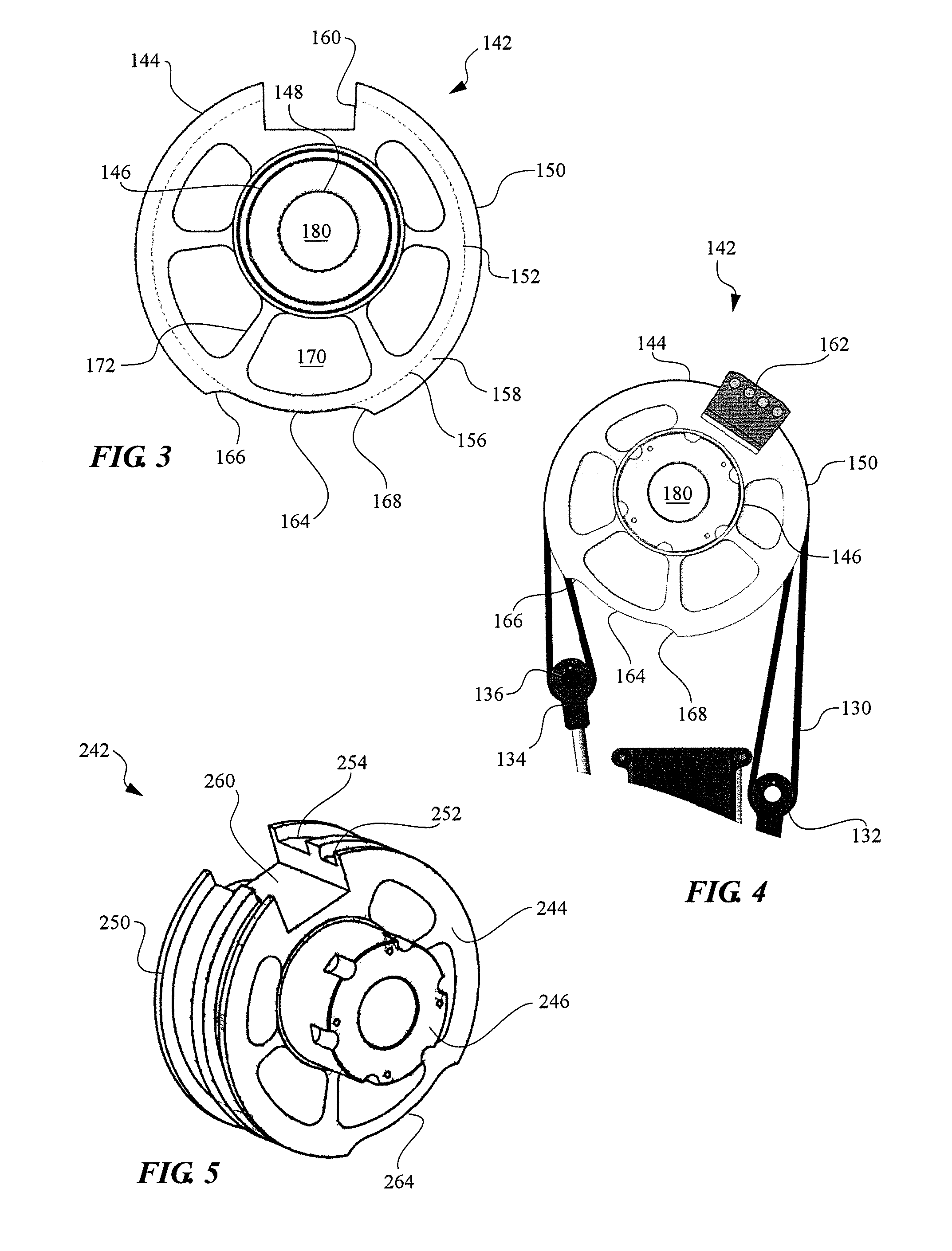
[0041]The circumferential outer surface 150 of the VR pulley 142 can be round, with the center hole 148 formed in a location that is off-set or eccentric from the geometric center of the round outer surface or disc body 144. The center hole 148 can further define the pivot point about which the VR pulley 142 rotates, so that the radial distance between the outer surface and the pivot point is variable along the length of the outer surface 150. Thus, a round pulley with an eccentric center hole 148 and axle portion 146 can form a VR pulley, as shown. In another aspect of the present invention, the VR pulley's disc body and outer surface may not be round, but instead can be an oblong, elliptical or some other non-round body or shape that provides the VR pulley with a continuously variable radius having more or less eccentricity than the round embodiment 142 with an eccentric pivot point illustrated in FIGS. 3-4.

[0042]The VR pulley 142 can include a cut-out notch 164 in the disc portio...

embodiment 200

[0049]The two symmetrically-sized actuators of each fractional antagonistic actuator pair 220, 230 can be linked together over the VR pulley 242 with tendons 280, 290. Although the tendons may be provided in a variety of shapes sizes, the tendons shown in the embodiment 200 can have a belt-shaped profile of defined width and thickness, and can further be configured with dimensions that match with the width and thickness of the corresponding tendon grooves 252, 254. Each tendon can be coupled at its midsection to the attachment block 262 connected to the VR pulley, which device can fix the tendons to the VR pulley and prevent slippage of the tendons within the grooves.

[0050]In the embodiment 200 shown, the tendons 280, 290 can be attached to the ends of the actuator pistons 226, 236 by looping the tendons through end connectors 282, 292 and coupling the ends of the tendons back to the coupling block 262. Additionally, each end connector can be configured with a connector rod 284 that...


PUM


Abstract

A biomimetic mechanical joint for generating a variable torque between support members of a biomimetic robotic device, including a base support member, a rotary support member rotatably coupled to the base support member, and a variable-radius pulley operably coupled between the base support member and rotary support member. The variable-radius pulley comprises a sheave body having a variable radius and one or more tendon grooves formed in the circumferential outer surface. The mechanical joint further includes one or more flexible tendons and antagonistic actuator pairs, with each actuator pair being coupled to one or more tendons and configured to operate the tendon around the variable-radius pulley in either direction to create a variable torque between the base and rotary support members.

Description

RELATED APPLICATIONS[0001]This application claims priority to U.S. Provisional Patent Application No. 61 / 092,699, filed Aug. 28, 2008, and entitled “Biomimetic Mechanical Joint,” which application is incorporated by reference in its entirety herein.FIELD OF THE INVENTION[0002]The field of the invention relates generally to exoskeletons and robots, and more specifically to the mechanical joints for exoskeletons and robots having natural or human-like characteristics.BACKGROUND OF THE INVENTION AND RELATED ART[0003]Significant advancements in the development of robots and robotic devices have been achieved in recent decades. Manufacturing efficiencies gained through the use of robotic assemblers and manipulators, exploratory robotic vehicles (such as those traveling the surface of Mars), and animatronics characters often seen at theme parks and other sights of attraction are but a few popular examples. Each of these specialized robots have common characteristics, however, in that they...

Claims


Application Information

Patent Timeline
IPC IPC(8): B25J17/00
CPCA61F2/68Y10T74/20323A61F2002/5093A61F2002/701A61F2002/704A61F2002/745A61F2002/747A61H3/008B25J9/0006B25J9/104A61H2201/14A61H1/0262A61H1/0266A61H3/00A61H2201/1215A61H2201/123A61H2201/1238A61H2201/1628A61H2201/164A61H2201/165A61H2201/1676Y10T74/20329Y10T74/20305A61F5/0102A61F2/70A61F2/74
Inventor JACOBSEN, STEPHEN C.OLIVIER, MAREI XMACLEAN, BRIAN J.
Owner SARCOS LC
Why Eureka
Try Eureka