Valve control system and valve control method

a valve control system and valve control technology, applied in water supply installation, process and machine control, instruments, etc., can solve the problems of complex system management, complicated system design, and complicated stock management, and achieve the effect of easy design and maintenan

Active Publication Date: 2011-09-08
ORMON CORP
View PDF7 Cites 5 Cited by
  • Summary
  • Abstract
  • Description
  • Claims
  • Application Information

AI Technical Summary

Benefits of technology

[0032]An object of the invention is to provide a valve control system and a control method thereof that allow easy design, maintenance and the like, and can meet the safety standards.

Problems solved by technology

For example, therefore, the following problems occur when the safety-standard-meeting valves are introduced into the existing system for constructing a system meeting the safety standards.
First, design of the system is complicated because the safety-standard-meeting valves that are the special parts are added to the existing system.
Therefore, the stock management becomes complicated, and the management for maintaining the system becomes complicated.
This restricts the system design.
Since the safety-standard-meeting valve is generally more expensive than the general-purpose valve, the cost for constructing and maintaining the system may increase.
Therefore, the arrangement of the safety-standard-meeting valves significantly restricts the design of the system.
Thus, the safety-standard-meeting valve restricts the flexibility in system design.
However, this structure results in a problem that a state (e.g., a slightly open state) intermediate between the completely open state and the completely closed state cannot be detected.
As described above, the conventional valve control system complying with the safety standards suffers from a problem that the structures and specifications of the safety-standard-meeting valves restrict the specifications of the system.

Method used


Image

  • Valve control system and valve control method
  • Valve control system and valve control method
  • Valve control system and valve control method

Examples


Embodiment Construction

[0063]Embodiments of the invention will now be described with reference to the drawings. In the drawings, the same or corresponding portions bear the same reference numbers, and description thereof is not repeated.

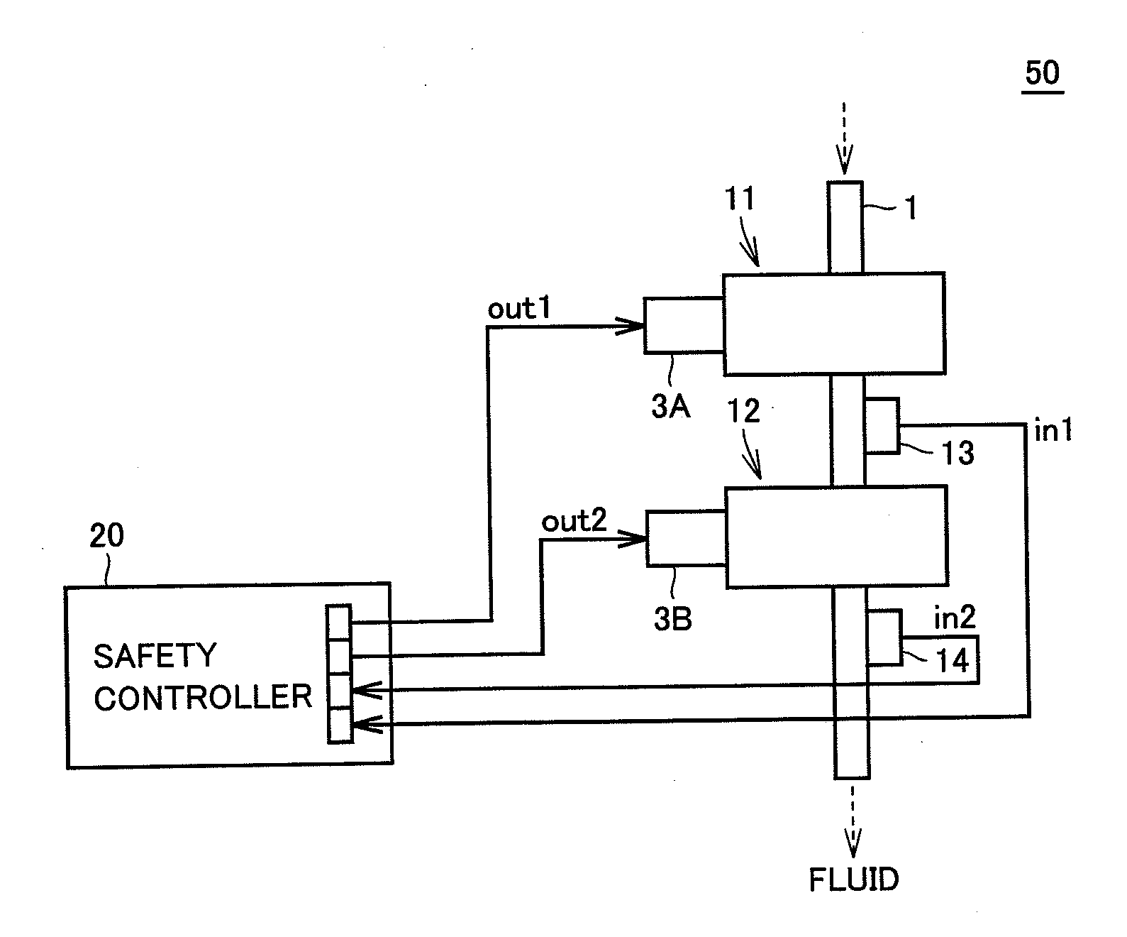
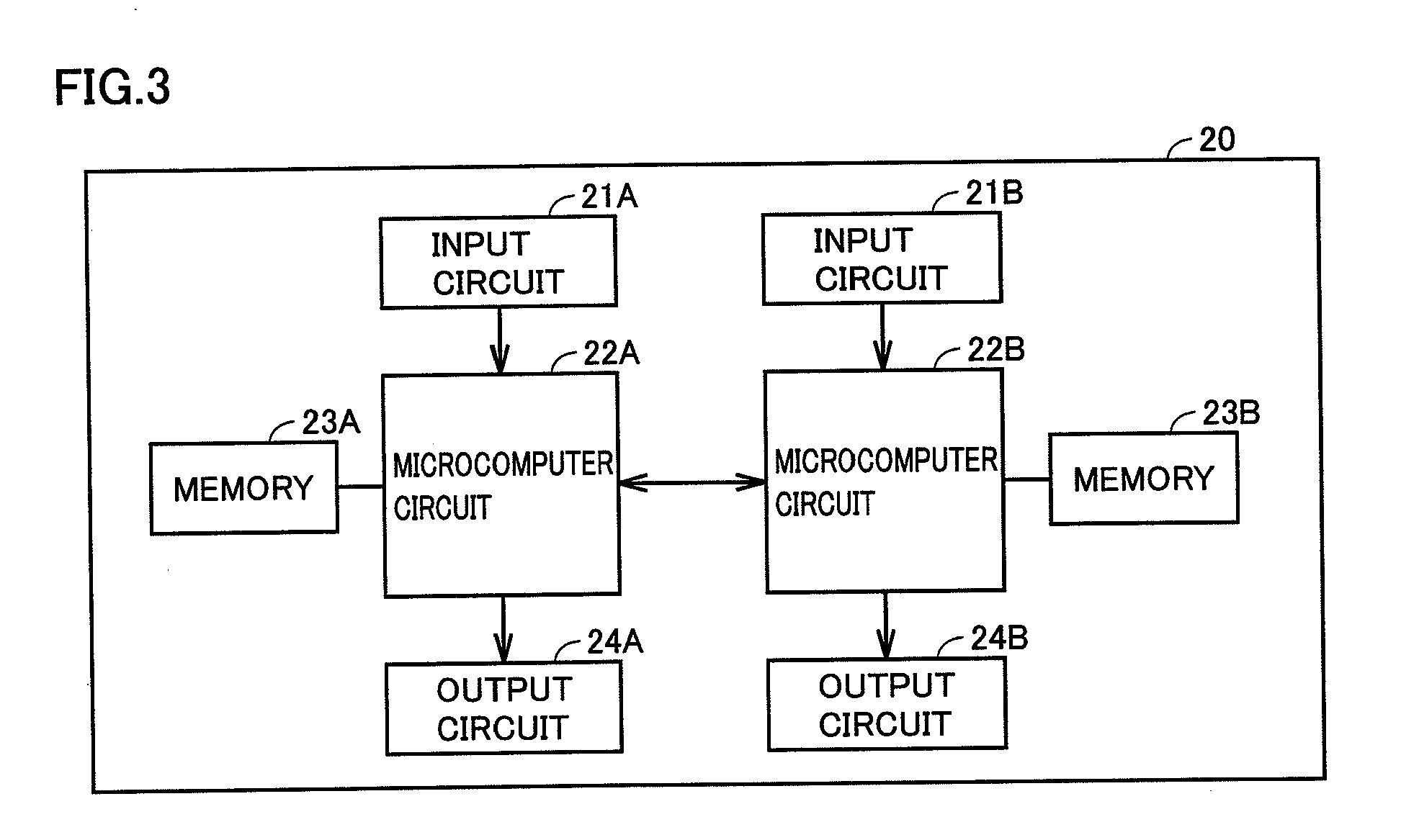
[0064]FIG. 1 shows a structure of a valve control system according to an embodiment of the invention. Referring to FIG. 1, a valve control system 50 includes valves 11 and 12, sensors 13 and 14, and a safety controller 20. Valve control system 50 is introduced into, e.g., a system of a factory.

[0065]Valves 11 and 12 are arranged on a pipe 1 that is a flow path of a fluid. Valve 12 is arranged in a portion of pipe 1 downstream from valve 11. The fluid flowing through pipe 1 may be either a gas or a liquid. Also, a specific kind of the fluid is not restricted. Further, a material, a sectional shape and the like of pipe 1 are not particularly restricted.

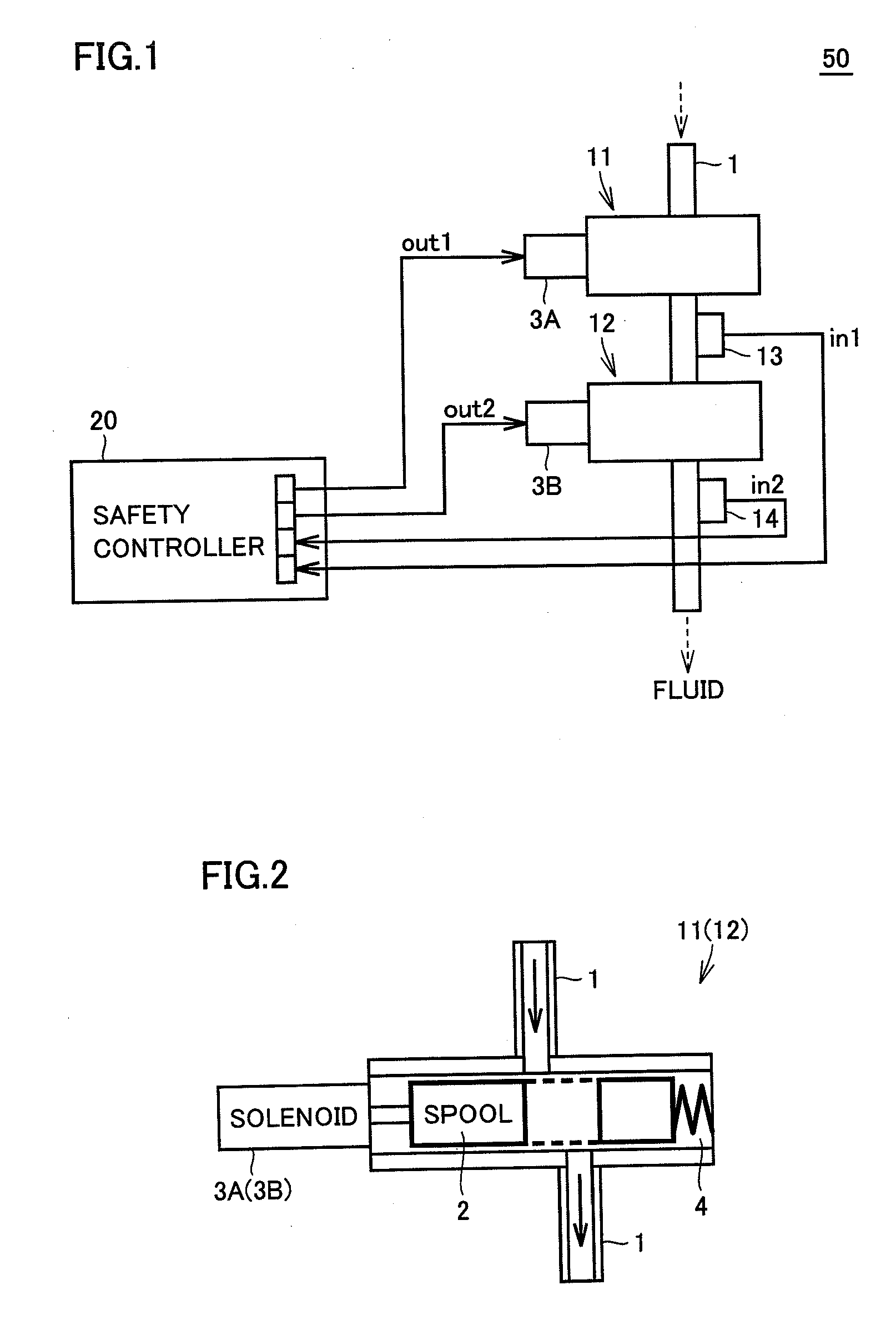
[0066]Valves 11 and 12 can be opened and closed by electric signals. Specifically, valves 11 and 12 are general-purpose sole...


PUM


Abstract

A valve control system includes general-purpose valves arranged in a pipe that allows the flow of fluid, first and second sensors, and a safety controller. The general-purpose valves are valves that can be opened and closed according to electric signals, and may be, e.g., solenoid valves, respectively. The first and second sensors are sensors that detect a state of fluid flowing from the corresponding valves, and are formed of, e.g., pressure switches, respectively. The safety controller may satisfy safety standards, and outputs signals for controlling the valves based on signals provided from the first and second sensors, respectively.

Description

[0001]This application claims priority from Japanese Patent Application No. 2010-047931 filed on Mar. 4, 2010 in the Japan Patent Office, the disclosure of which is incorporated herein by reference in its entirety.BACKGROUND OF THE INVENTION[0002]1. Field of the Invention[0003]The present invention relates to a valve control system and a valve control method, and more particularly to a valve control system and a valve control method that can meet safety standards.[0004]2. Description of the Background Art[0005]FIG. 13 illustrates an example of a conventional general-purpose valve. Referring to FIG. 13, a valve 101 is arranged in a pipe 1 through which a fluid (e.g., air, water, oil or the like) flows. Valve 101 can be opened by an electric signal, and specifically is a solenoid valve.[0006]A spring 104 pushes a spool 102 so that valve 101 is normally closed. When the electric signal turns on a solenoid 103, solenoid 103 moves spool 102. Thereby, valve 101 opens. When solenoid 103 is...

Claims


Application Information

Patent Timeline
Patent Type & Authority Applications(United States)
IPC IPC(8): F16K31/02
CPCG05D7/0647Y10T137/0318Y10T137/7761Y10T137/86389
Inventor IZUTANI, HAJIMEMATSUMOTO, TSUYOSHISHIMOHARA, FUMIHARU
Owner ORMON CORP
Why Eureka
Try Eureka