Paired optically variable security element

a security element and optical variable technology, applied in the field of security documents, can solve the problem of not being able to achieve the same spectral characteristics using different quarter-wave or half-wave designs

Active Publication Date: 2011-09-08
SICPA HLDG SA
View PDF13 Cites 15 Cited by
  • Summary
  • Abstract
  • Description
  • Claims
  • Application Information

AI Technical Summary

Benefits of technology

[0044]The invention comprises further a set of first and second optically variable coating compositions, in particular inks, for embodying a paired optically variable security element, said first coating composition containing a first optically variable interference pigment having a first dielectric of a lower refractive index (nlow), and whose kth-order reflection maximum (k) shows a shift from a first reflection wavelength (λ1) at orthogonal incidence to a second, shorter wavelength (λ2) at grazing incidence, and said second coating composition containing a second optically variable interference pigment having a second dielectric of a higher refractive index (nhigh), and whose same kth-order reflection maximum (k) shows a shift from a third reflection wavelength (λ3) at orthogonal incidence to a fourth, shorter wavelength (λ4) at grazing incidence, wherein the range spanned up by said third and said fourth wavelengths of said second pigment is within the range spanned up by said first and said second wavelengths of said first pigment.

Problems solved by technology

The principal shortcoming of the device of WO 96 / 39307 is that the required “same hue” of the first and the second pigment at one determined angle of incidence must be produced through different spectral characteristics, because it is impossible to realize the same spectral characteristics using different quarter-wave or half-wave designs.

Method used


Image

  • Paired optically variable security element
  • Paired optically variable security element
  • Paired optically variable security element

Examples


example

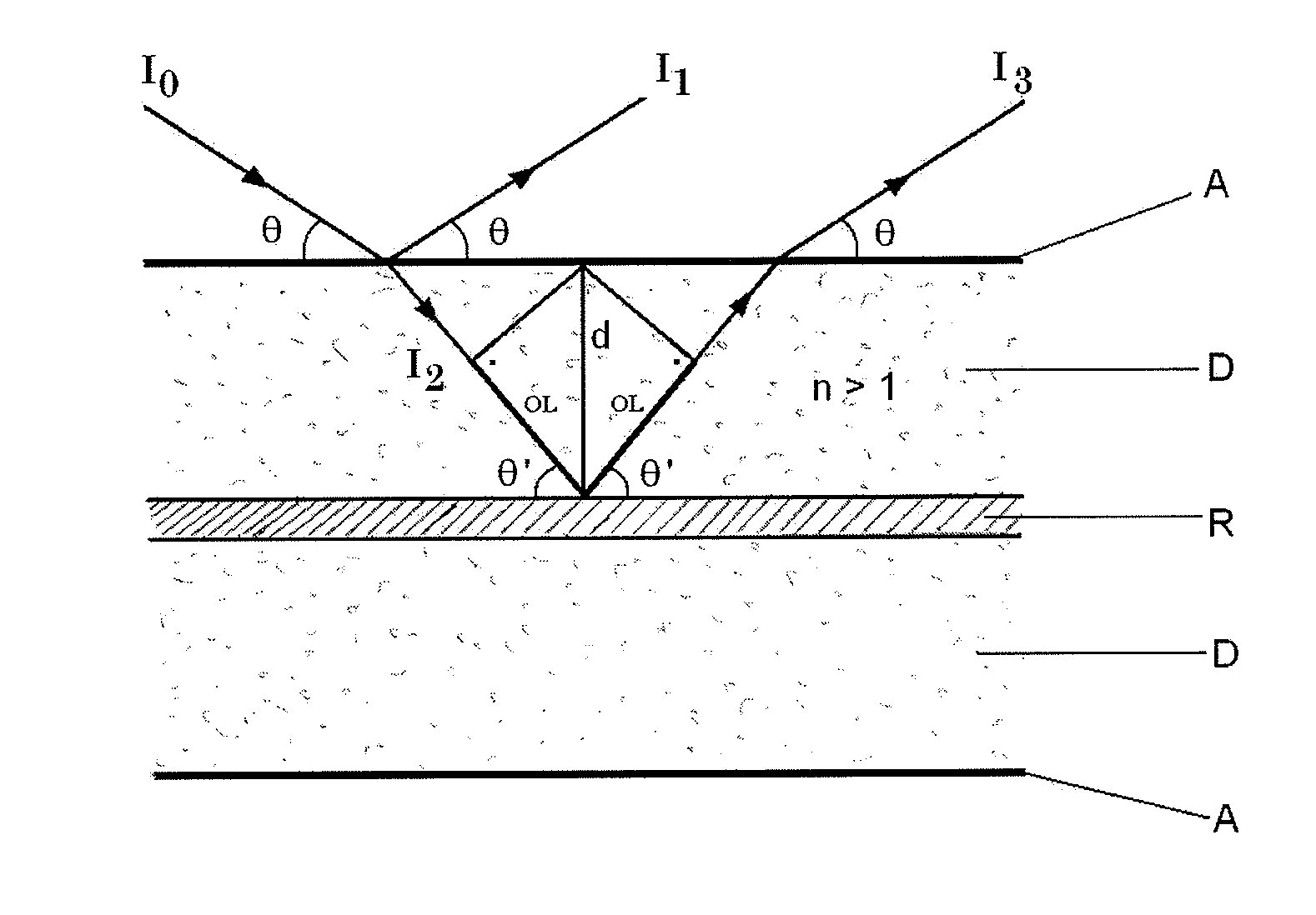
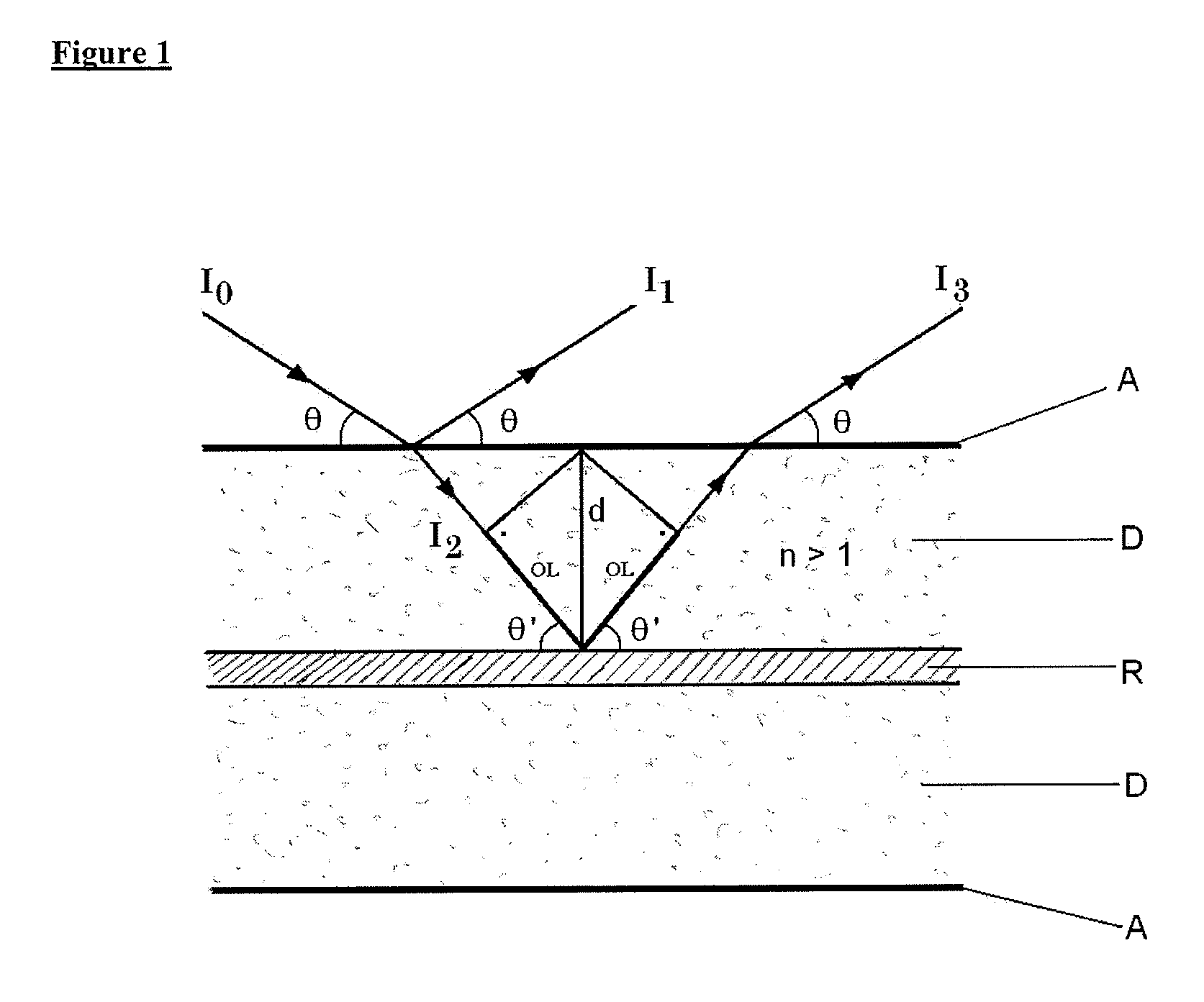
[0071]First and second optically variable interference devices were prepared by the successive physical vapor deposition of the different layers of each a symmetric half-wave metal-dielectric interference design onto a release-coated PET carrier foil.

[0072]Chromium (Cr), Magnesium fluoride (MgF2; n=1.35), Yttrium oxide (Y2O3; n=1.89), and Aluminum (Al) were deposited as know to the skilled person and described in the cited state of the art references, noteworthy using electron-beam assisted evaporation sources in a high vacuum.

First Device

[0073]Symmetric design of the absorber / dielectric / reflector / dielectric / absorber type, having the following layer sequence:[0074]1. Absorber layer: Cr, 3.5 nanometers[0075]2. Dielectric layer: MgF2, 490 nanometers (n=1.35)[0076]3. Reflector layer: Al, 40 nanometers[0077]4. Dielectric layer: MgF2, 490 nanometers (n=1.35)[0078]5. Absorber layer: Cr, 3.5 nanometers

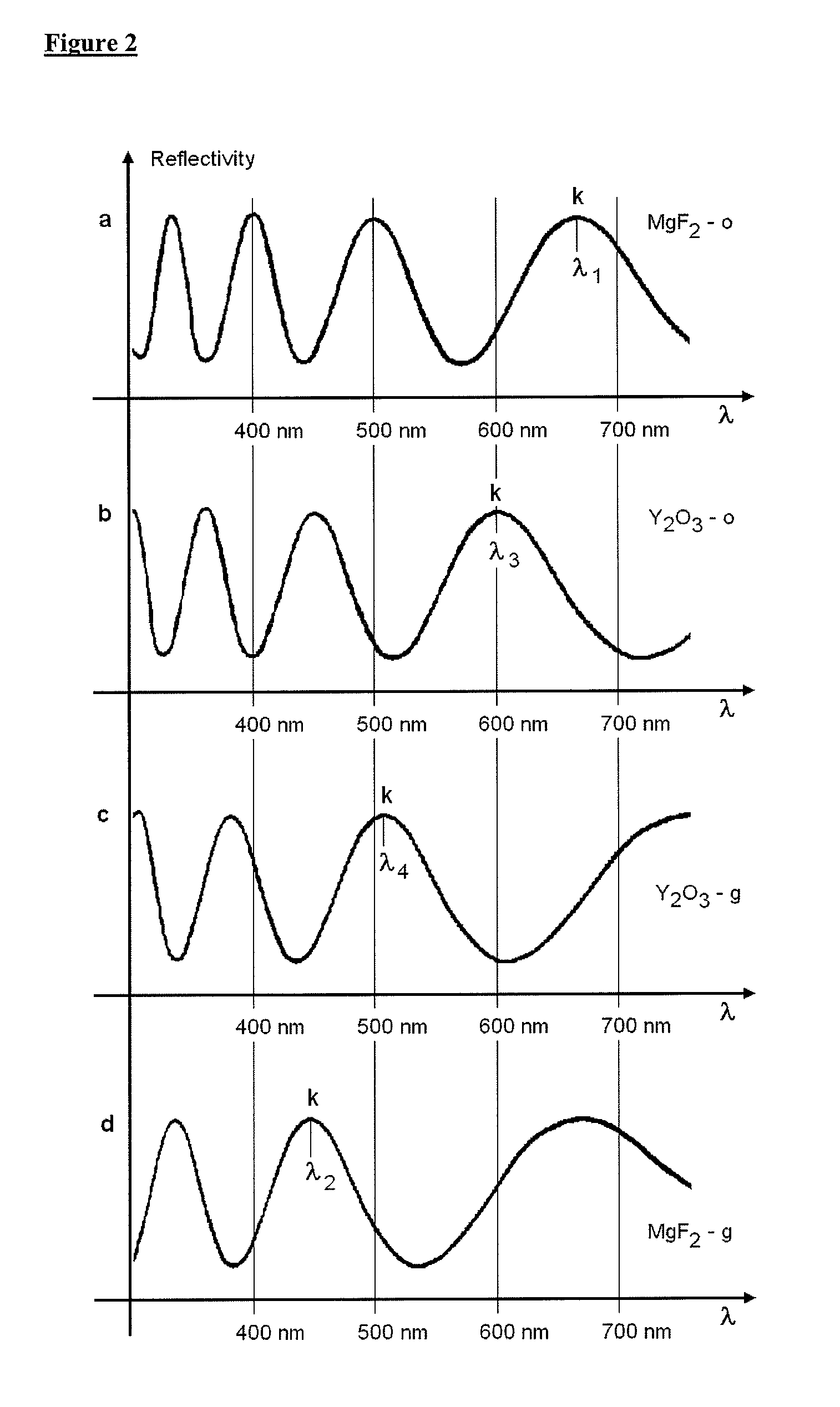
[0079]Design for 2nd-order reflection maximum (k=2) at 660 nm under orthogonal incidence;...


PUM

PropertyMeasurementUnit
angleaaaaaaaaaa
angleaaaaaaaaaa
refractive indexaaaaaaaaaa

Abstract

Disclosed is a paired optically variable security element which comprises first and second optically variable thin-film multilayer interference devices in the form of optically variable foils or of printings made with inks comprising optically variable interference pigments, wherein said first and second interference devices exhibit spectral matching at a determined angle of incidence. Sets of optically variable devices and of coating compositions comprising optically variable pigments for the production of said paired optically variable security element are also disclosed, as well as the use of said security element for the protection of documents and goods, and security documents and goods carrying same.

Description

FIELD OF INVENTION[0001]The present invention is in the field of security documents. It concerns a paired optically variable security element which comprises first and second optically variable interference devices in the form of optically variable foils or of printings made with ink comprising optically variable interference pigments, wherein said first and second interference devices exhibit spectral matching at a determined angle of incidence. Sets of optically variable devices and of inks or coating compositions comprising optically variable pigments for the production of said paired optically variable security element are also disclosed, as well as the use of said security element for the protection of documents and goods, and security documents and goods carrying said security element.BACKGROUND OF THE INVENTION[0002]Optically variable foils, optically variable pigments (OVP), and coating compositions comprising OVP, noteworthy optically variable ink (OVI®), are known in the f...

Claims


Application Information

Patent Timeline
Patent Type & Authority Applications(United States)
IPC IPC(8): B42D15/00C09D11/02B32B37/02B32B37/14B05D5/06B05D1/36
CPCB42D2035/24B42D2035/26Y10T156/10G02B5/286B42D25/29B44F1/10B42D25/328B42D25/355B42D25/364B42D25/373B42D25/378B41M3/14G02B5/28
Inventor BLEIKOLM, ANTONDEGOTT, PIERREMUELLER, EDGAR
Owner SICPA HLDG SA
Why Eureka
Try Eureka