Detachable electrical power receptacle
- Summary
- Abstract
- Description
- Claims
- Application Information
AI Technical Summary
Benefits of technology
Problems solved by technology
Method used
Image

Examples
first embodiment
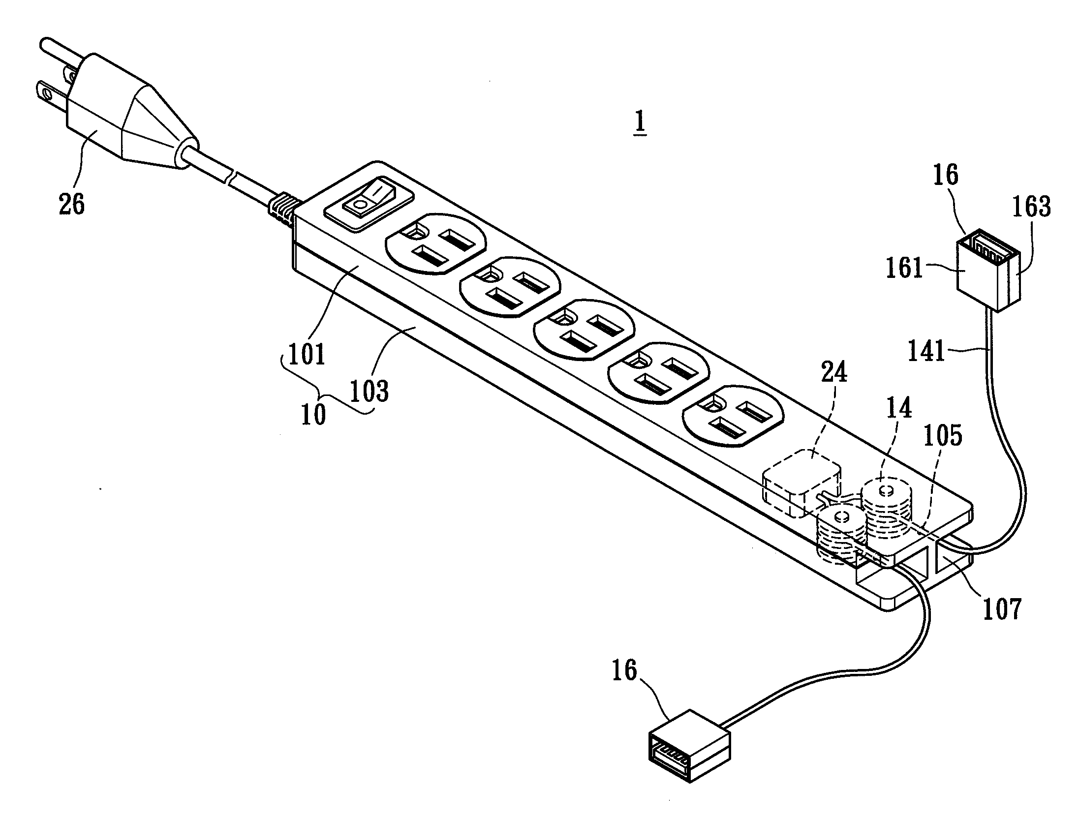
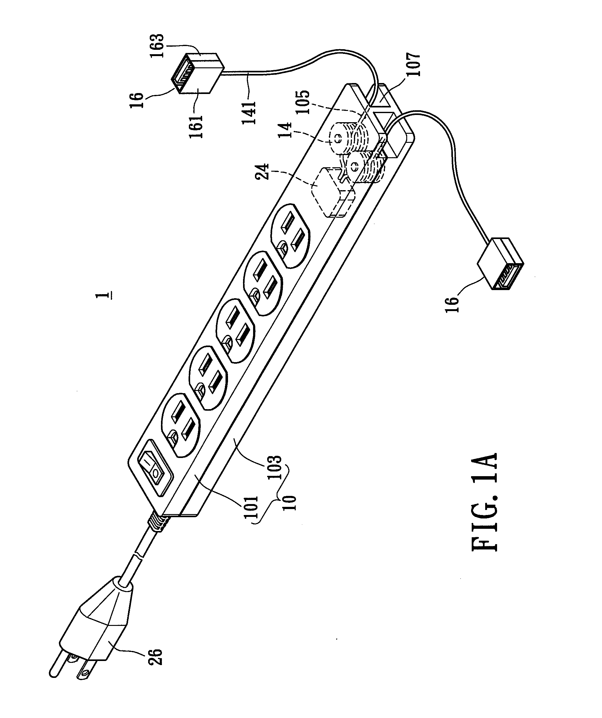
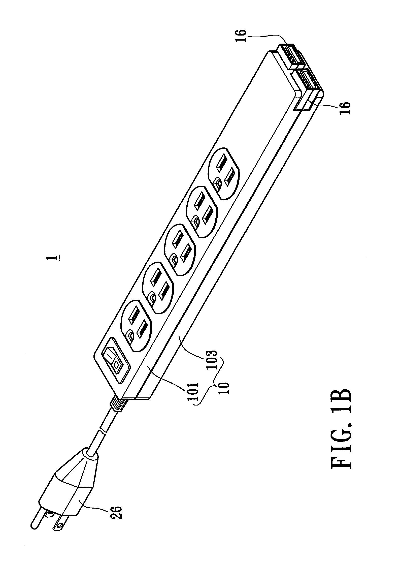
[0017]First please refer to FIG. 1A, in which an exploded diagram of the detachable electrical power receptacle in accordance with certain aspects of the present technique in an exposed mode is demonstrated. A detachable electrical power receptacle 1, comprises a main body 10, at least one extension socket 16, at least one extension power cord 141, a coil reel 14, a power unit 24, and an electrical power plug 26. The main body 10 further includes a first housing member 101, a second housing member 103, at least one outlet hole 105, and an accommodating section 107. The extension socket 16, includes a third housing member 161 and a fourth housing member 163.
[0018]The main body 10 is formed by connecting the first housing member 101 to the second housing member 103. The main body 10 has the electrical power plug 26 which functions by electrically connecting a power supply source and has the outlet hole 105. The outlet hole 105 may be designed to allow the extension power cord 141 wrap...
second embodiment
[0022]Please refer to FIG. 2 in conjunction with FIG. 1A, in which an exploded diagram of the detachable electrical power receptacle according to the present invention is demonstrated. A detachable electrical power receptacle 1a has identical components and similar connecting relationship with respect to that of FIG. 1A and FIG. 1B. The only structural difference, however, is a location design regarding the accommodating section 107a. As shown in FIG. 2, the accommodating section 107a has a first accommodating space 1070 and a second accommodating space 1072. The first accommodating space 1070 is disposed on a periphery of the main body 10a and the second accommodating space 1072 is disposed on a middle section of the main body 10a. Furthermore, an extension power cord 141 passed thru an outlet hole 105 adjacent to the first accommodating space 1070 connects to a first USB (Universal Serial Bus) jack 165; an extension power cord 141′ passed thru an outlet hole 105′ adjacent to the s...
PUM
| Property | Measurement | Unit |
|---|---|---|
| Length | aaaaa | aaaaa |
| Power | aaaaa | aaaaa |
| Distance | aaaaa | aaaaa |
Abstract
Description
Claims
Application Information
 - Generate Ideas
- Intellectual Property
- Life Sciences
- Materials
- Tech Scout
- Unparalleled Data Quality
- Higher Quality Content
- 60% Fewer Hallucinations
Browse by: Latest US Patents, China's latest patents, Technical Efficacy Thesaurus, Application Domain, Technology Topic, Popular Technical Reports.
© 2025 PatSnap. All rights reserved.Legal|Privacy policy|Modern Slavery Act Transparency Statement|Sitemap|About US| Contact US: help@patsnap.com