
Confocal microscope system

a microscope system and confocal technology, applied in the field ofconfocal microscope systems, can solve the problems of large space, large inconvenience, and the breadth of the system as a whole, and achieve the effect of compact siz

Active Publication Date: 2011-09-08
YOKOGAWA ELECTRIC CORP
View PDF7 Cites 8 Cited by
  • Summary
  • Abstract
  • Description
  • Claims
  • Application Information

AI Technical Summary

Benefits of technology

[0017]It is one of illustrative aspects of the present invention to provide a confocal microscope system configured so as to be compact in size without the needs for a large space, requiring fewer spots for adjustment.

Problems solved by technology

The scanner unit, in particular, is often connected to a side-port of a microscope, in which case, a problem has arisen in that the system as a whole has increased in breadth, requiring a large space.
Furthermore, there has existed another problem that even after accurate positional adjustment is once made on a laser beam to be guided to an optical fiber, and the laser beam is further guided to the scanner unit again, it has been necessary to make accurate adjustment on the angle as well as the position of the laser beam, thereby causing much inconvenience.

Method used


Image

  • Confocal microscope system
  • Confocal microscope system
  • Confocal microscope system

Examples


Embodiment Construction

[0027]The present invention is described in detail hereinafter with reference to the accompanying drawings.

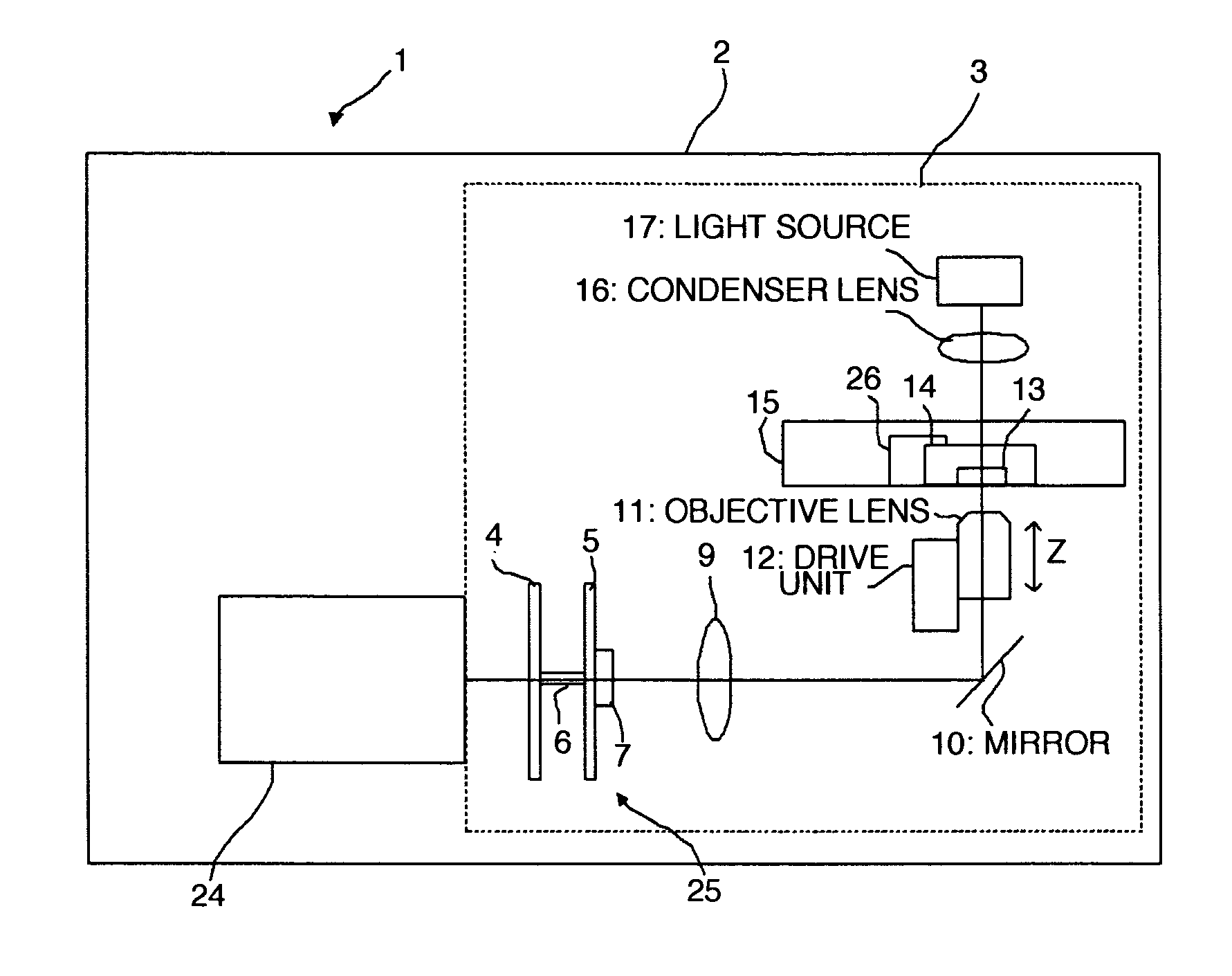
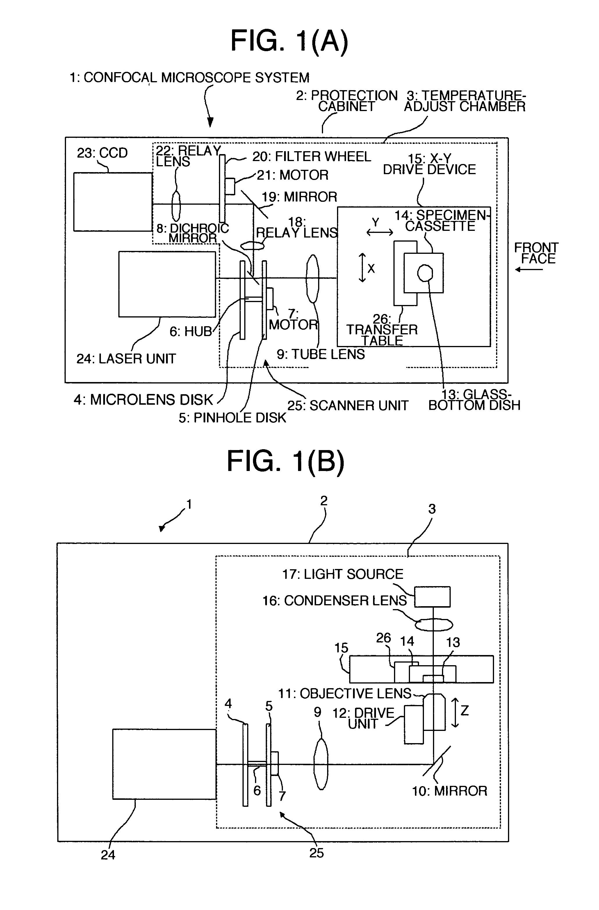
[0028]FIGS. 1(A), 1(B) each show one embodiment of a confocal microscope system according to the invention, in which FIG. 1(A) is a plan view thereof, and FIG. 1(B) is a front view thereof.

[0029]In FIGS. 1(A), 1(B), the confocal microscope system 1 is covered with a protection cabinet 2. A temperature-adjust chamber 3 is installed in the protection cabinet 2, the temperature-adjust chamber 3 being for use in adjusting an internal temperature thereof so as to be kept at a constant temperature (for example, at 30° C.). A face of the protection cabinet 2, on an observer's right side, is a front face, and the temperature-adjust chamber 3 is disposed such that the right side face thereof lies along the front face of the protection cabinet 2.

[0030]An X-Y drive device 15 is disposed on a side of the temperature-adjust chamber 3, adjacent to the front face of the protection cabinet 2, ...


PUM


Abstract

There is provided a confocal microscope system configured so as to be compact in size without the needs for a large space, requiring fewer spots for adjustment. In the confocal microscope system, respective units making up the confocal microscope system are integrally housed in a protection cabinet covering the confocal microscope system, and when a specimen disposed opposite to an objective lens is moved toward an external face of the protection cabinet, a side of the external face, adjacent to an opening through which the specimen is taken in, or out, is defined as a front face, the Nipkow disk type scanner unit is disposed backward of the objective lens.

Description

[0001]This application claims priority from Japanese Patent Application No. 2010-045102, filed on Mar. 2, 2010, the entire contents of which are herein incorporated by reference.BACKGROUND[0002]1. Technical Field[0003]The invention relates to a confocal microscope system, and in particular, to a confocal microscope system wherein respective units making up the confocal microscope system are integrally combined together in an attempt to achieve improvements on installation space.[0004]2. Related Art[0005]With a confocal microscope system according to the present invention, the focal point of a laser beam, over a specimen, is scanned, and a returning florescent beam from the specimen is caused to form an image to obtain an image of the specimen, thereby carrying out observation on the specimen. Thus, the confocal microscope system is in use for making an observation on morphological observation as well as physiological response of a living cell, in the fields of a living organism, bio...

Claims


Application Information

Patent Timeline
Patent Type & Authority Applications(United States)
IPC IPC(8): G02B21/06
CPCG02B21/24G02B21/0044
Inventor NEZU, TAICHIROUKEI, TAKAYUKIHIRUKAWA, HIDEOKUWABARA, YOHEITAKAI, HIRONORI
Owner YOKOGAWA ELECTRIC CORP
Learn More